
x2Originally Posted by Blue86


x2
- Scott -
- PAST CARS
- 84 Capri
- 96 SHO
- 88 Mustang GT
- 87 Mustang GT
- 79 Capri -351W
- 79 Mustang
Dean I put more tint on my sun roof to make it darker. I am thinking of doing a another layer to make it even darker yet lol.
84 Mustang GT, 91 roller motor,Gt40 heads, vic jr intake, quickfuel 650 carb, MSD ignition, TFS stage 1 cam, 3.73gears in 8.8, rear disc conversion, some nitrous.


wow. I'm impressed. Had no idea you were modifying so much. You've come along far!
Where is it at now??
Jeremy
-86 mustang SSP X CHP Unit # 3788-bone stock & staying that way
-66 Mustang, bench seat car,8.8,t5 fuel injected 92 engine
-72 Maverick 5.0 resto in process
-12SS Camaro 6 speed. 600 FWHP, Kraftwerks Supercharger
-03 z71 Avalanche 9" lift on 35s Daily Driven 20k a year. 290k miles at 11.8 mpg
Entire 1986 electrical and vacuum troubleshooting manual download
http://slantnosefox.com/picturehosti...g%20manual.zip

looks great. i like modifyied stangs lot better than any factory stock one. look forward to more photos.

Hi all, haven't progressed too far after getting the T-5Z in and "placing" the X-pipe in. The X-pipe needs to be tweaked a bit to fit right. Anthonydarlymple gave out some pointers in another post of mine about "adjusting" the X-pipe to fit.
MutantCapri1979: Sorry I didn't notice your question earlier. I really don't know the differences in the spare tire well of an '84 versus a '79 through '81. I do know the '78-'79 (not sure about the '80-'81s) Fairmont spare tire well is deeper than an SEFI Mustang tire well.
Anyway, I probably should wait on the final tweaking until I get the rebuilt roller engine in with the headers attached. In the mean time I really should finish up the brake conversion, swap in the driver side Sn95 spindle, and make a decision on the SEFI wiring.
Dean T
Proud owner of the one and only Friggin' Futura
After two years, I finally got the urge to continue work on the '84. I started to look into mating the '84 wiring to the suppose '90 SEFI main harness I have.
First of all, I had to sort through the '84's underhood engine harness to figure out what stays and what gets pulled out of the wiring harness.
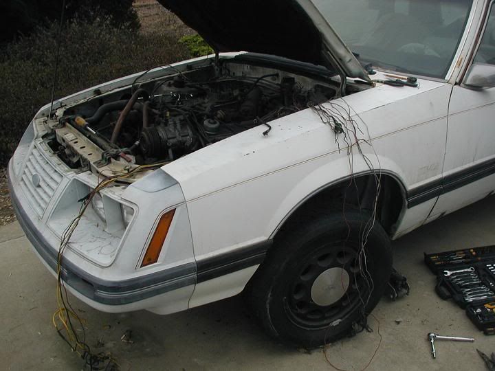
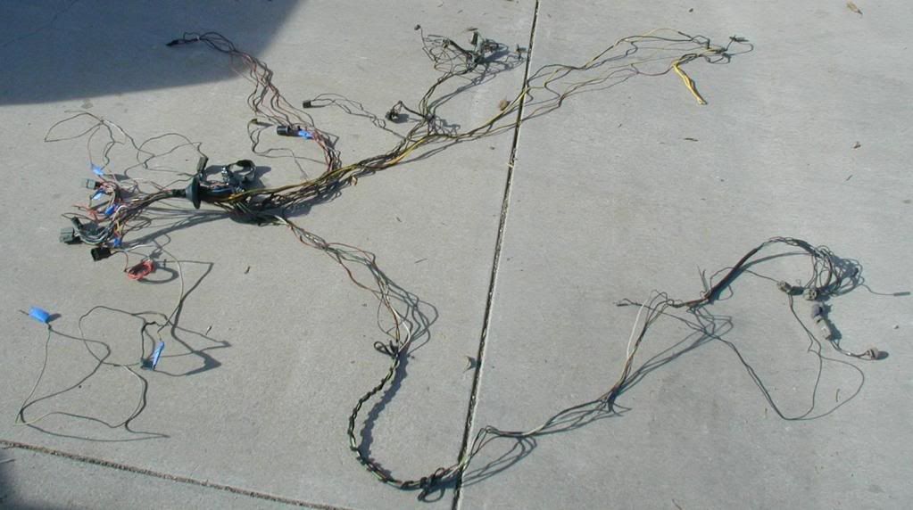
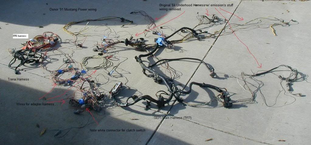
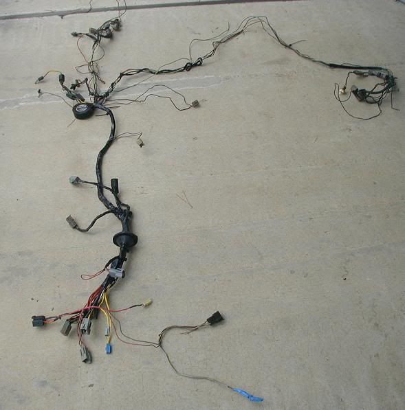
Here is the full underhood harness before I started
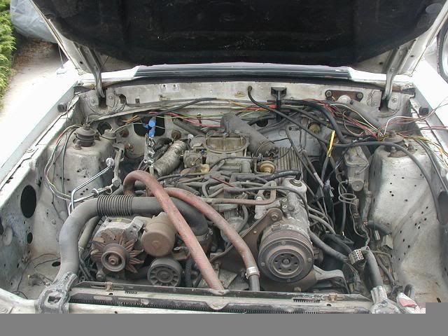
This is how it looked after I pulled off all the '84 emissions electricals and move all the wiring from the starter solenoid from the passenger side to the driverside where the SEFI Mustangs have their solenoids located.
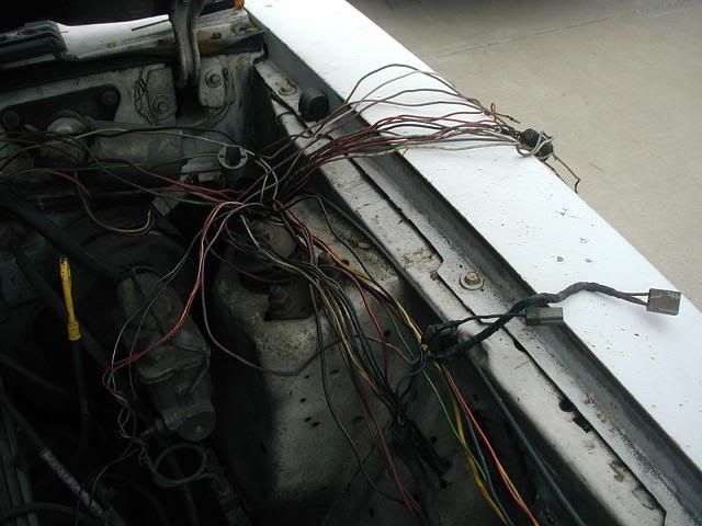
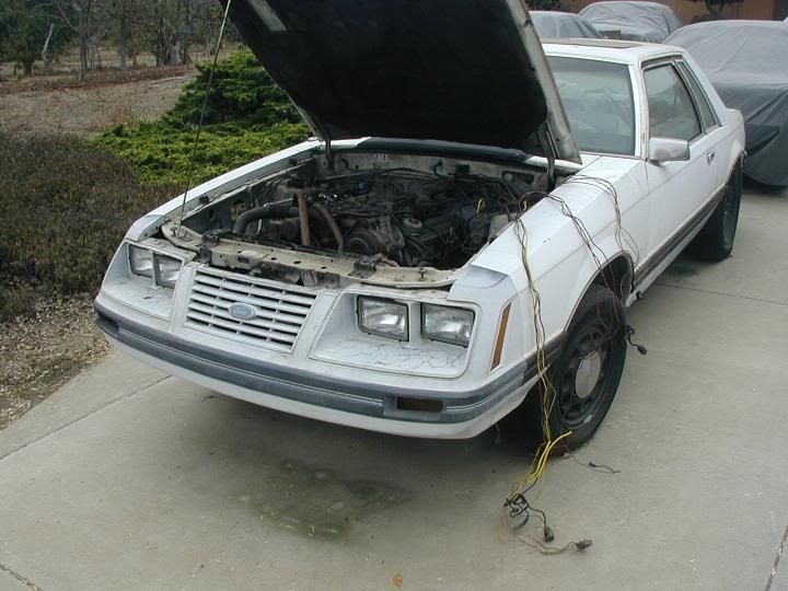
On the driverside fender, I separated the wires to be ripped out. The bunch along the top used to go to the Duraspark module, voltage regulator, a/c clutch, a/c pressure switch, coil, distributor, and a bunch of silly emissions related electrical doohickys. That's the technical terms for them - I looked it up!
here you can see the yellow wires which goes to the battery side of the starter solenoid.
Here is a last shot of the underhood electricals before I said "heck with it, I'm yanking everything!" and then proceeded to remove the entire wiring harness from the car. I did this so I can get access to all the connectors which I need inorder to figure out which wires I need to interface with the suppose '90 main SEFI Mustang wire harness.
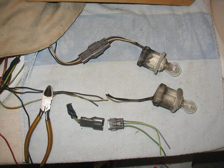
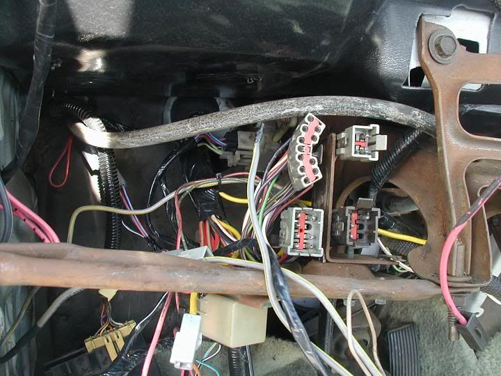
While I'm tearing my hair out figuring out how to do this and finding out exactly what SEFI main harness I actually have, here's a tutorial on replacing the Salt and Pepper connectors found on the SEFI main wiring harness as well as the SEFI engine harness.
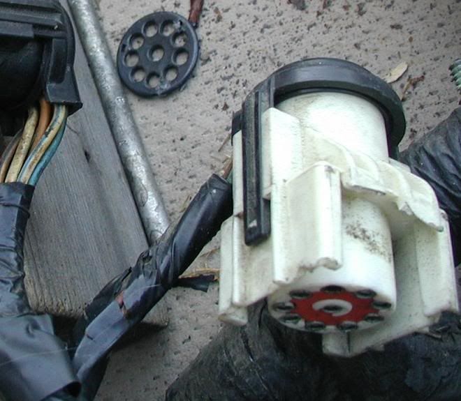
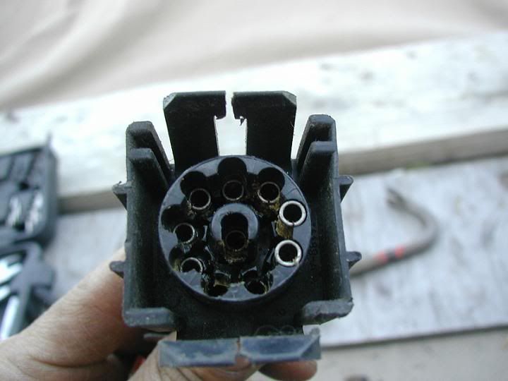
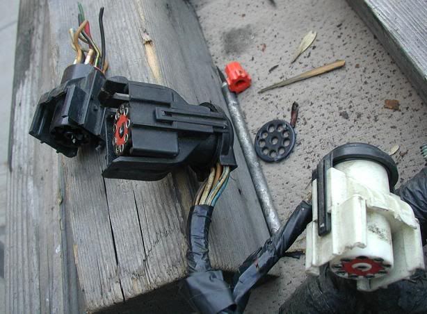
Here is what some of us face when we buy a wiring harness from idiots who don't know how to read the direction on the connector to separate them. Note the busted white connector - Einstein previous owner managed to break both clips. Note the black connector - I already had repaired it before thinking of taking pictures.
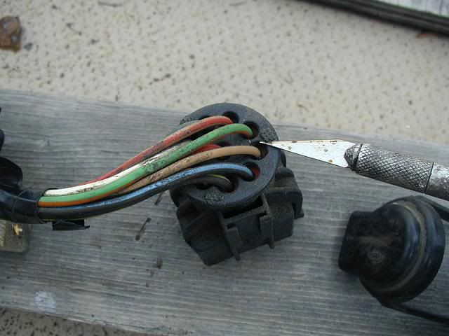
The first thing to come off is the protective cap over the wires going into the connector. You can gently lift the tabs of the black cover over the locking tab with your bare hands. You will have to do this and subsequent steps twice if you are swapping a broken connector with an unbroken donor connector.
Now you can see a ring in which all the wires pass through. Unfortunately, this ring is held in by pins on the main connector which has been heat sealed. I used an Exacto knife to cut the seals.
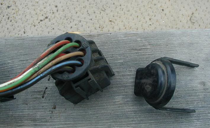
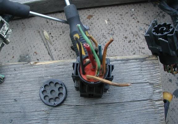
Here is the connector without the ring. The connector you are replacing you will not be able to remove the ring - just slide it up the wires to get it out of the way. You will need this ring when it all goes back together.
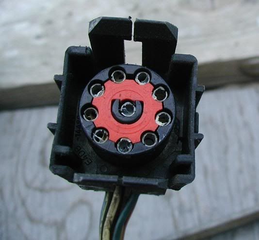
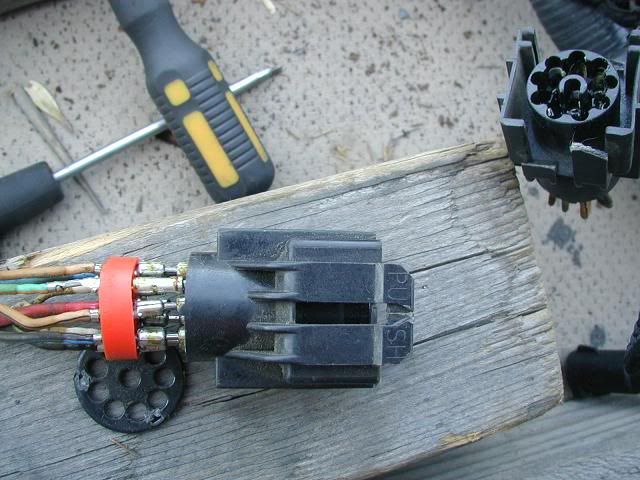
Flip the connector over and use a small screw driver (a Jeweler's srew driver works well) to pry the big red thing out.
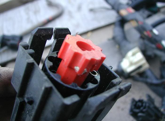
The big red thing looks like this and keeps the pins from being pushed out easily.
With the red thing gone, you can release each pin and push them down. Don't push them out all the way yet.
I suggest pulling the pins out of the donor connector first. Then note the pin positions and wire colors relative to the U shape center section of the broken connector and pull the wires out. Push the entire wire bundle into the donor connector in the same position as the broken connector. Don't clock the wires off even by one or you're toast.
Now start reversing the order of disassembly to reassemble by first making sure all the pins are locked in before reinstalling the red thing. The ring can be resecured by RTV or JB Weld or some such adhesive that won't melt the connector, the wires, or your hands.
And badda-bing! Done!
Last edited by Dean_T; 11-06-2010 at 12:23 AM.
Proud owner of the one and only Friggin' Futura
cool to see this worked on again. We may have to chat...I'll be modifying an 89 harness for my maverick...
btw i've got an extra injector harness and 02 harness for an 89 setup if you find that's the main harness that you have
Jeremy
-86 mustang SSP X CHP Unit # 3788-bone stock & staying that way
-66 Mustang, bench seat car,8.8,t5 fuel injected 92 engine
-72 Maverick 5.0 resto in process
-12SS Camaro 6 speed. 600 FWHP, Kraftwerks Supercharger
-03 z71 Avalanche 9" lift on 35s Daily Driven 20k a year. 290k miles at 11.8 mpg
Entire 1986 electrical and vacuum troubleshooting manual download
http://slantnosefox.com/picturehosti...g%20manual.zip
So it's two months later, where am I at? Much further than what I can show here because I haven't had a chance to take more pics.
But, here is my '84's Underhood harness which enters the firewall near the brake power booster.
Here is all the stuff it either has to interface with or needs to assimulate inorder to interface with the SEFI Main harness - which I'm still not sure if it's a '90 or '91. It has wire color codes like the '91 but pins out similar to the '90. Oh well.
Couple of interesting bits:
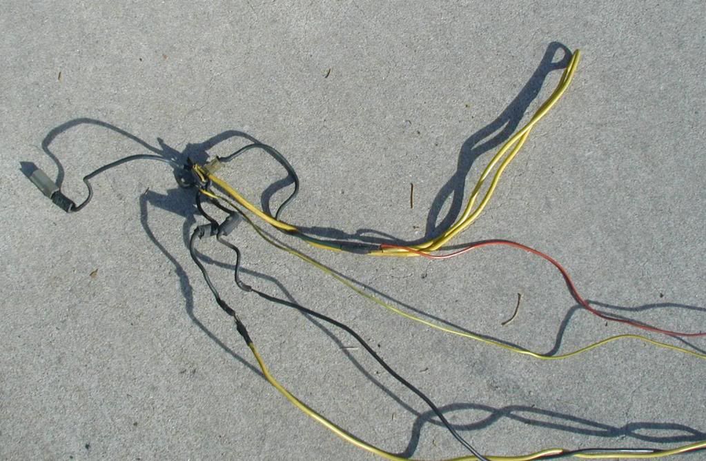
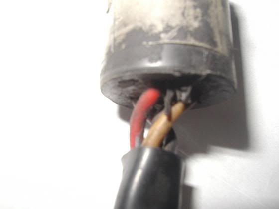
Here is the '84's ammeter wiring - yellow-green and red-orange wires with a "hunk" of large gauge Yellow wire inbetween.
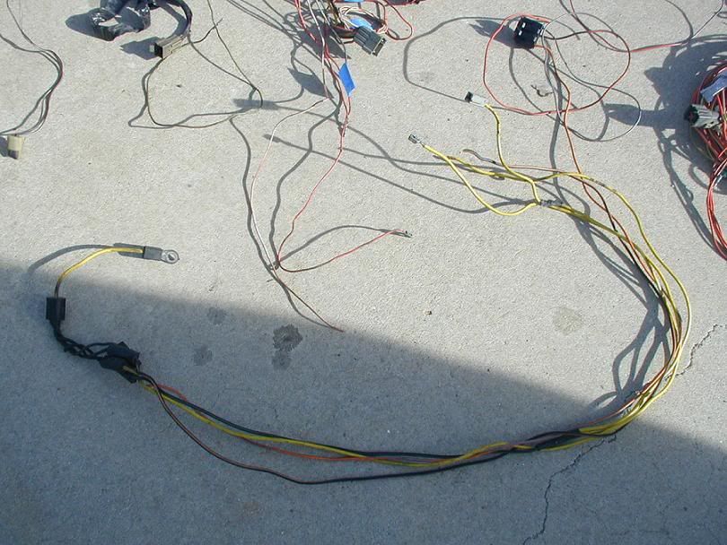
Here is the power wiring I grabbed from a '91 aero because Ford had the Fuel Pump Relay power feed connected to a fusible link rather than directly to the battery. I wanted to make my SEFI wiring close to Ford so I can either look up the wires in an '84's EVTM or a '90 or '91 EVTM.
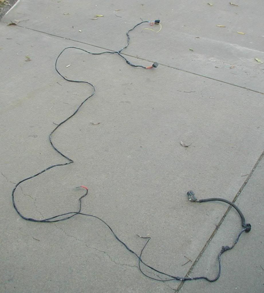
The easiest wire harness to recreate is the Fuel Pump Relay (FPR) harness.
I think I grabbed this one in it's entirety from an '89 or so Mustang. I had to separate it from the tail light harness because I wanted to keep my '84 tail lights. I wrapped the donor harness with self stick adhesiveless tape. I don't like gummy electrical tape.
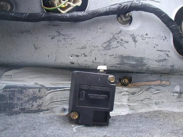
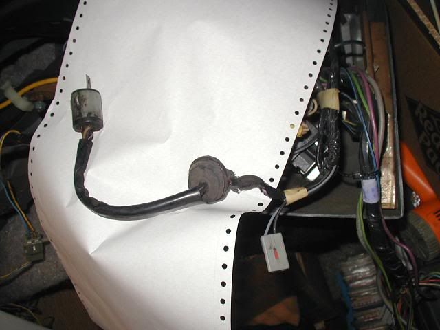
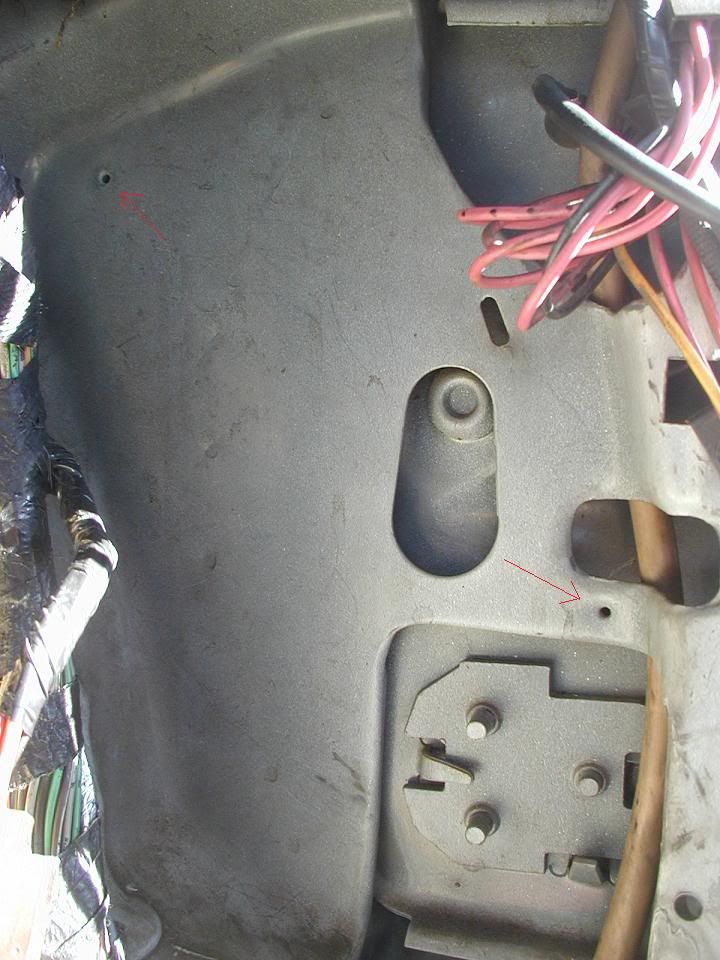
Thank Ford for CFI '84 Mustangs. I was scratching my head trying to figure out where to mount the inertia switch and then I saw the light -er, dimples.
Switch and wiring installed:
Looks factory! (although I have the original fuel sender wiring tucked in behind the tail panel brace - couldn't bear to chop the last unchopped major wire harness on the car.
Routed the wiring as Ford would have - if they had a separate harness.
And bam! Fuel Pump Relay and FPR harness 12-pin connector with the Yellow-White fuel gauge sender wire installed in the '84's driver side 8-pin green connector (not to be confused with the SEFI main harness 8-pin green connector next to the EEC).
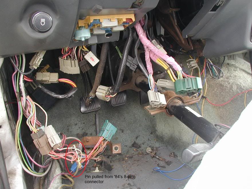
Here's an important pic I'll be referring to later. Note the '84's fuel gauge sender wire already pulled from the '84's 8-pin green connector. The connectors just peaking out under the fuse box are going to be important later, when I show the adapter harness I constructed to tie the '84's Underhood harness, the Trans harness, the SEFI Main Harness, the Cruise Control Brain box, and the '84's Dash harness all together.
Speaking of the trans harness, it is integral with the '84's Dash harness and pops out under the dash near the console, sneaks under the rug and goes through a hole in the trans tunnel. Ford, thinking like a good mouse, has a second hole in the trans tunnel for the VSS wires for the Cruise Control.
I hated the big ol' humongus busted-up trans connector Ford used for the '84 Mustang and like the '87 and later connectors instead. So I grabbed one from an '89 or so. It has the trans, VSS, and Neutral Sensor switch wiring all in the same harness. I'm going to have an extra hole in my trans tunnel but, oh well.
Anyway, the '84 has 4 wires going to the trans, Red-light blue, White-pink-dot, Purple-orange-hash, and black-purple. I don't care about the R-LB wire because the 8-pin trans connector in my adapter harness (grabbed from a '90 Mustang) already has this wire and the jumper from the white-purple wire which I will feed with the W-PK-D because this is where the '84 trans got the power for the R-LB wire for the starter solenoid wire (via the clutch start switch). The P-O-H and BLK-P wires are the '84's back-up light wiring which in my '90 Mustang adapter harness is P-O and BLK-P
Okay,
The next two pictures are very important - it took me over two years to create them and design the adapter harness.
Study them, take notes because there's going to be a test when I get back.
Adapter harness (Fixed again 1/19/11):
Pin-out for whatever the heck year SEFI harness I have ( I think it's a mutant '90 - just learned '91s had a single brown 8-pin connector rather than a grey 8-pin connector and a black 8-pin connector).
Good night!
Dean T
Last edited by Dean_T; 01-19-2011 at 10:28 PM.
Proud owner of the one and only Friggin' Futura

That makes me cringe. Too many wires. I recognized the ammeter wiring right away. I got to know that very well when my car refused to charge. You have a lot of patience, keep it up!!

Very impressive. The sight of all those wires just makes my eyes glaze over.
1986 Black GT with T-tops
damn Dean....you're in it neck deep....that's some sick amount of work.
couple of questions cause i'm about to do this to the maverick.
1. I heard the efi harness is near stand alone...needs to have power supplied and ground...wouldn't it be easy to just splice the harness in?
2. Places like ford fuel injection offers a $475 harness that's plug and play for efi conversions basically.....would it be ez to just swap that in???
sorry for the noob questions...this just seems like so much work!
Jeremy
-86 mustang SSP X CHP Unit # 3788-bone stock & staying that way
-66 Mustang, bench seat car,8.8,t5 fuel injected 92 engine
-72 Maverick 5.0 resto in process
-12SS Camaro 6 speed. 600 FWHP, Kraftwerks Supercharger
-03 z71 Avalanche 9" lift on 35s Daily Driven 20k a year. 290k miles at 11.8 mpg
Entire 1986 electrical and vacuum troubleshooting manual download
http://slantnosefox.com/picturehosti...g%20manual.zip
Jeremy,
I did make this harder on myself by wanting to stick with either '84 or '90 or so Ford wire colors and use an adapter harness so I can separate the Dash harness, fuel pump relay harness, the SEFI main harness, and the '84's Underhood harness from each other for debugging or maintenance purposes.
Aftermarket harnesses are fine if they include EVERYTHING including the oxy sensor harness and fuel pump relay harness. A person still has to determine all the pick-up points for the various power wires and I would want some of those power wires to be fused as Ford has done, either by fusible links or Maxi fuses. An example is the fuel pump relay - Ford had an 18 gauge fusible link so I didn't feel comfortable just running a wire to the battery terminal on the starter relay.
I design and do this type of stuff for a living so it was easier for me to do what I did. It's all a matter of keeping track of the go-in-uz and the go-outs-uz.
Dean T
Proud owner of the one and only Friggin' Futura
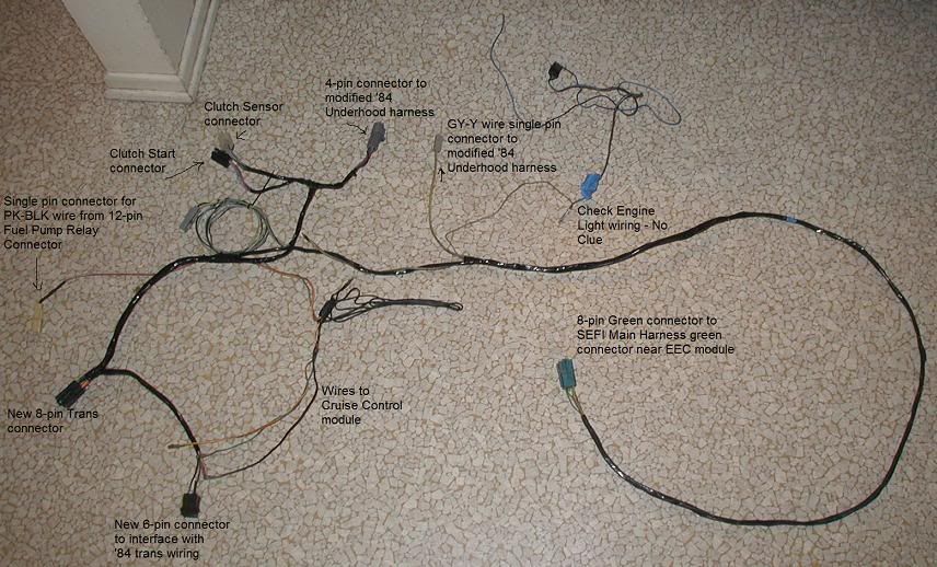
Okay folks, Remember the schematic wiring diagram for the Adapter harness? Here's what it looks like in real life. The only thing I still haven't done is resolve how the Check-Engine light is wired up. When I do, I plan to use a stand alone bulb that fits in one of the sockets running vertically on the LH side of the dash. I'll have to change the particular lens of the dash faceplate to say "Check-Engine" to make it complete.
I could have cleaned up the harness a bit by getting rid of the extra connector from the Clutch/Neutral sensor circuit and the black ground wire from the VSS circuit but I have this feeling they could be useful.
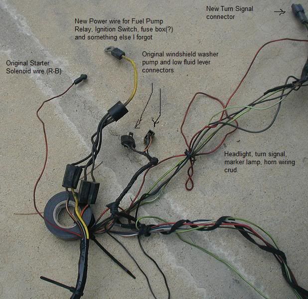
Here is the modernized Modified '84 Underhood harness. I haven't finished the tape wrapping due to the head light relay plans and the dang fusible link in the GY-Y wire busted off but otherwise, this baby is done!
The only untouched connectors in this end are the windshield wiper connector and the odd 11-pin grey connector. All other connectors are either new or modified!
Without the emissions wiring, '84 ignition wiring, and the '84's power wiring this harness cleaned up quite a bit. The new aero Mustang power wires look like they belong. The R-B wire to the solenoid is original but I clipped it from the original wiring. It is now directly attached to the new 4-pin grey connector and goes to the clutch start switch - which also serves double duty as the clutch sensor switch. The original '84 clutch start switch has two connector ports so adding the white connector is a snap! Of course I chucked my '84's black clutch start connector because the aero donor harness I used for the adapter harness already had the black and white connectors.
Did you notice the turn signal connector? Don't bother looking for it on your '84, it doesn't have one. Ford, in their infinite stupidity, didn't make the turn signal bulb sockets small enough to clear the '84's radiator support or front nose without either cutting the wiring or removing the nose. Since I don't want to mess up the alignment of the car's front nose ( I even tossed an aluminum front bumper because I couldn't install it without messing up the nose) I cut the turn signal bitches.
I found suitable connectors under the hood of a '97 or so Thunderbird.
Next I will be repairing the JY dash shell and fabricating an anti-mouse screen for the HVAC inlet (probably mount it inside the cowl right on top of the top-hat hole for the HVAC).
Once I double check some things on the SEFI harness, I hope to install the dash and all wiring and be done with the electricals - until I go to All Light Off...
Dean T
Last edited by Dean_T; 01-19-2011 at 10:17 PM.
Proud owner of the one and only Friggin' Futura

WOW!
That's a lotta thinkin' there Pilgrim!
Looks great and many "not having to think about it" days ahead for you!
-Bill
"Beater" ('82 Capri No Eng/NoTrans)
Wife's Project Car ('83 Vert Stang GLX No Eng/NoTrans)
"Cinco" ('88 Hatch Stang LX 5.0L/Manual)
"Bertha" ('92 Hatch Stang LX 2.3L/Manual)
'13 Ford Flex Platinum (Hers)
Husband & father of 3 girls
Thank you!
I had to go back and fix some of the designations and pictures. I mis-labeled the 8-pin Green connectors (as 6-pins) and screwed up some wire colors but all pics are correct and the connector and wire colors I've typed are correct.
As far as I can tell...
Dean T
Proud owner of the one and only Friggin' Futura
Good job dean. it seams like years ago since I did the same thing.
84 Mustang GT, 91 roller motor,Gt40 heads, vic jr intake, quickfuel 650 carb, MSD ignition, TFS stage 1 cam, 3.73gears in 8.8, rear disc conversion, some nitrous.
More than a month later, the Dash assembly is finally back in the car! Whoohoo!
First, I wanted to show the passenger kick panel area on my '84. As it turns out, Ford thoughtfully punched the holes for the computer bracket. CFI is a good thing...
Next, I installed the computer bracket and attached the EEC Relay to it.
I didn't forget the ground wire next to the computer connector. Ford also pre-punched this hole. Thank you CFI!
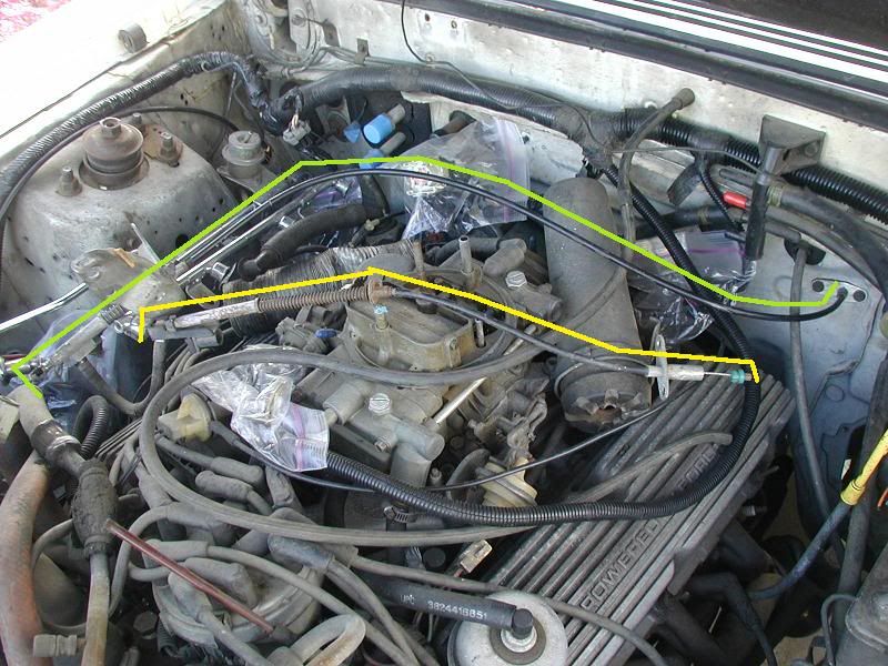
Installing the computer bracket was much easier without the dash assembly and HVAC in the way. Something else which was easy to replace was the throttle cable. As you can see, the '84's carb throttle cable (yeilow) is a wee bit shorter than the SEFI throttle cable (green).
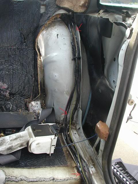
On to the dash assembly re-install. First, I had to install my modified '84 Underhood harness on the driver side. This is the hole (driver side, as view from inside the car) I have to stuff it through.
This is how it looks after cramming the modified '84 Underhood harness through the hole and double checking the firewall grommet is properly installed.
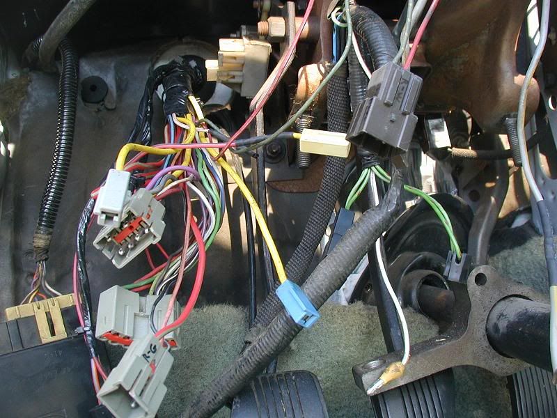
Here is a shot I should have taken before I yanked these connectors out when I started this SEFI conversion mess. These are the connectors from the modified '84 Underhood harness mounted on the porkchop brace. I think I may have transposed the grey 4-pin connector with the brown 6-pin connector. The grey-pin connector from the dash harness has shorter wires than the brown 6-pin connector wires coming from the dash harness. Not a problem until removing or installing the dash assembly.
A closer look at the porkchop brace connectors.
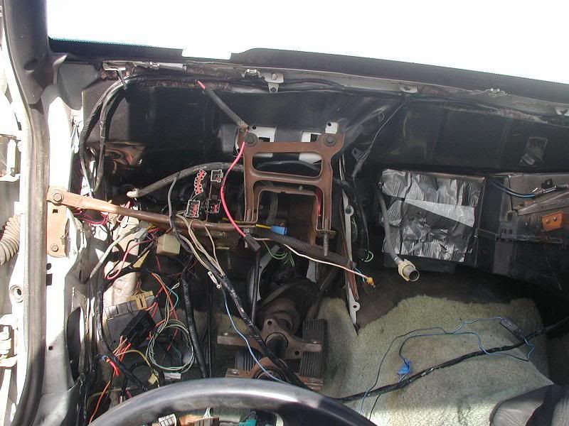
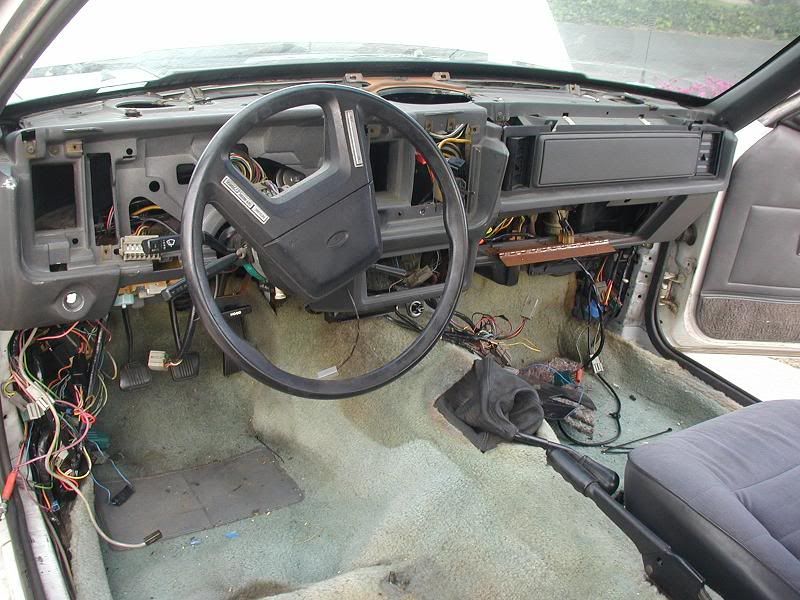
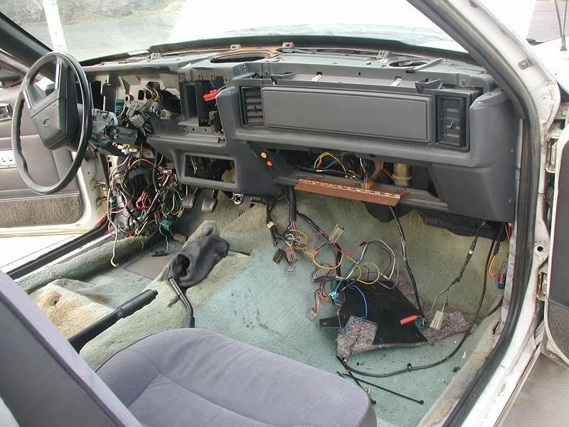
And a sight I thought I'd never see again, dash assembly and steering column all bolted back together.
View from the passenger side.
It was starting to get dark and a line from a Charlton Heston movie kept running through my head "My God, it's almost dark... They'll be waking up soon!". Okay, I watched all the wrong movies as a kid.
Note the dash shell is not from an '84. I harvested it from an '86 coupe and still had to use generous amounts of JB Weld and Gorilla Glue to repair it. It did quite well.
Next is to connect all the wires together and dress the wiring harness. I still need to install the new trans harness, HVAC controls, instrument cluster, and the broke-arse dash pad.
After that, I'm not sure what to tackle next. The front suspension still needs to be finished (a-arms, springs, maybe modify the K-member), Brakes (Cobra style and need to install the driver side Sn95 spindle), headlights (doing the relay conversion) and there's tons of the little stuff to finish the SEFI conversion (mounting all the SEFI periphials, E-coil, SEFI battery tray, air box) A/C parts, interior (bolt in the seats, replace qtr panel, install console,) install shifter, and need a drive shaft.
Still a long ways before this car hits the street...
Dean T
(I should have at least spelled the actor's name right!)
Last edited by Dean_T; 02-14-2011 at 01:24 AM.
Proud owner of the one and only Friggin' Futura

Good God man, I think I'm dizzy from all that, this harness that harness mumbo jumbo.
I'll just go back to block sanding for now. I hate wiring by the way.
Great job and very informative though.
Mike
1986 ASCMclaren #108
stock short block, Victor EFI, 75mm TB, 3.08's, Borla cat-back, slot style MAF conversion, Gt-40p heads, TFS1 cam, 80lb injectors, 69mm turbo, Moates Quaterhorse, E85. 501/584 @ the rear wheels
In all my wiring frenzy, I forgot about the trans harness. I used one from a '90 or so Mustang.
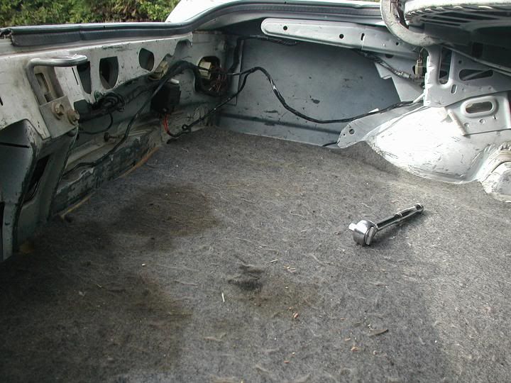
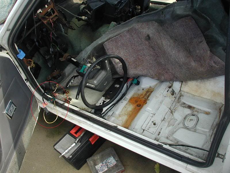
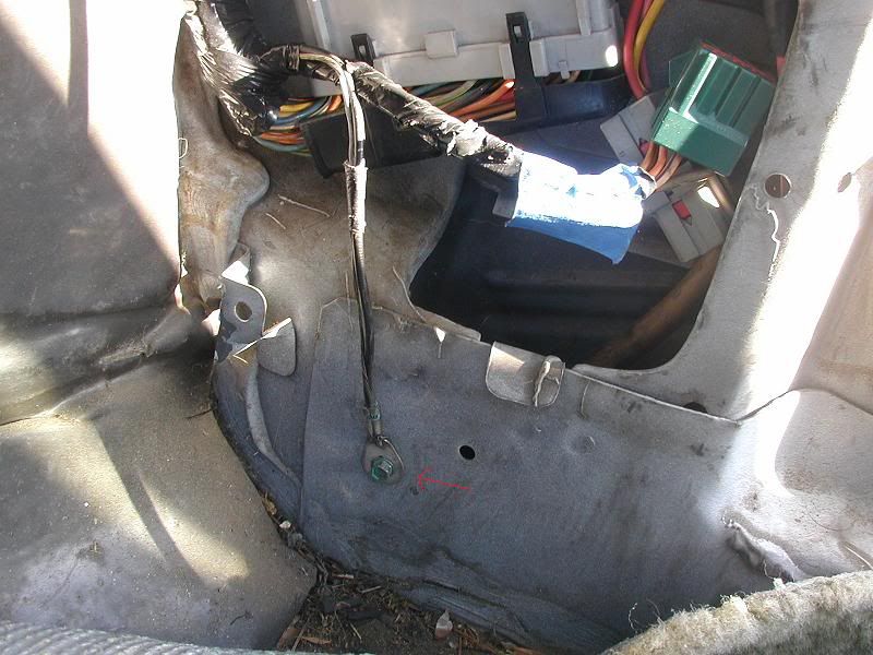
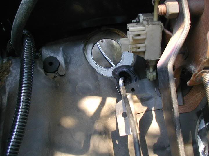
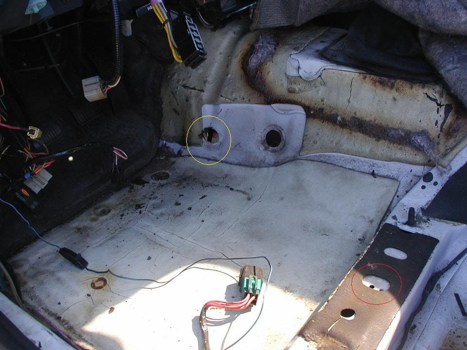
Remember I mentioned the '84 had two holes in the trans tunnel? The oval hole (marked by yellow circle) is where the VSS wiring went through. My '90 or so trans harness goes through the oval hole. The round hole for the '84's original trans harness will have to be plugged.
Note the holes in the red circle.
Did you see the ignition switch plug hanging? My original ignition switch came apart when I was tearing everything out. It was vintage '84 - the security screws were still intact.
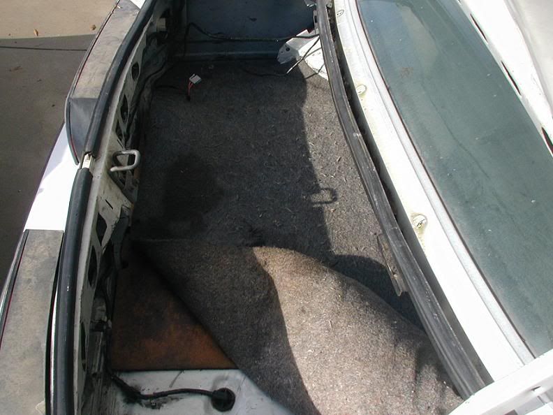
This picture shows the trans harness installed. I routed it like the orignal '84's trans harness only because I forgot how a '90 Mustang routes the trans harness.
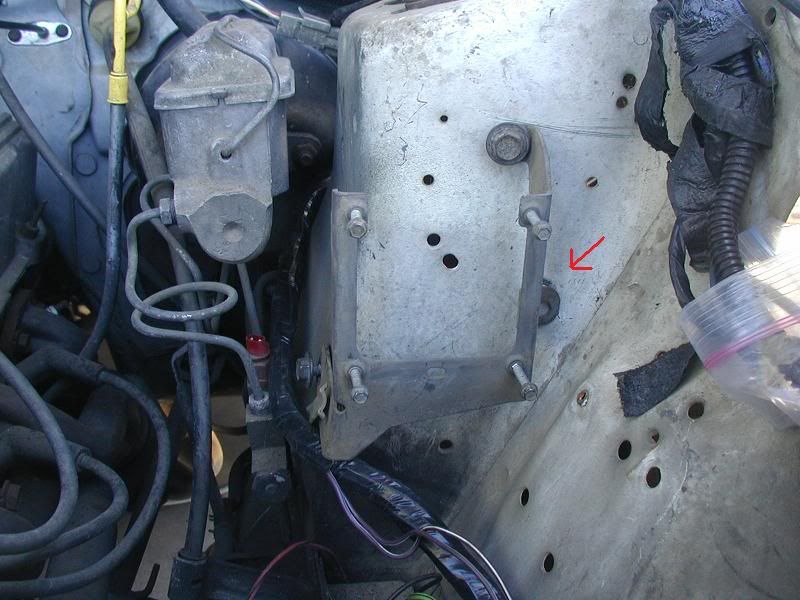
Once again, Thank Ford for CFI. The fuel pump relay bolted right in the hole marked by a red circle in the previous picture.
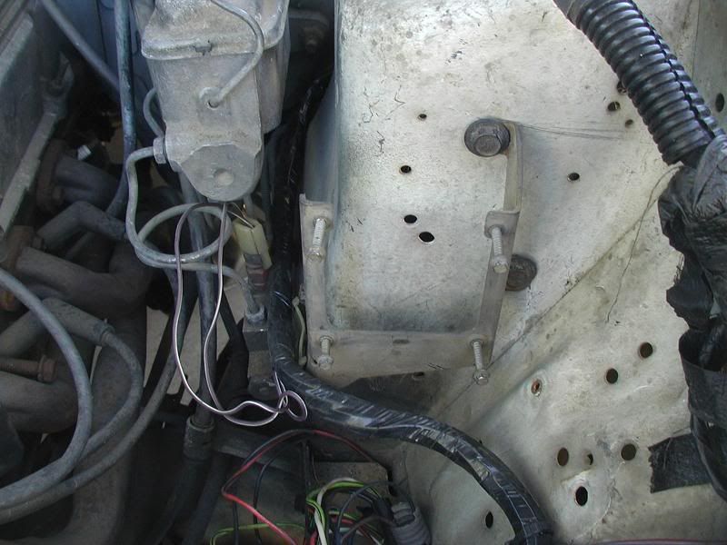
Jumping into the engine bay, I decided to mount the coil bracket. One hole did not line up.
What I did was cut the bracket where the hole didn't line up so I can stuff a bolt through the bracket. It's hardly noticable. Funny how the other two holes were dead on.
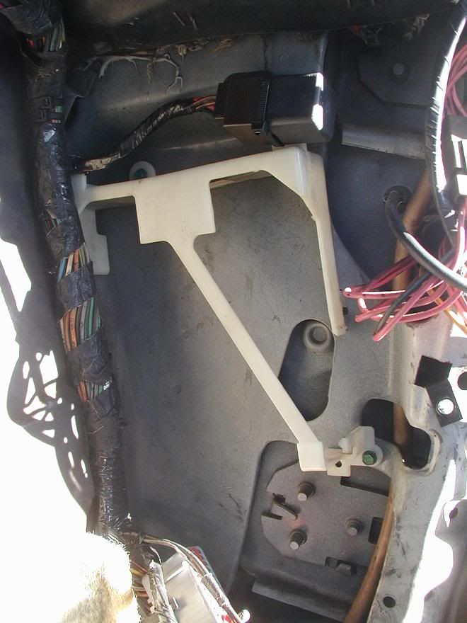
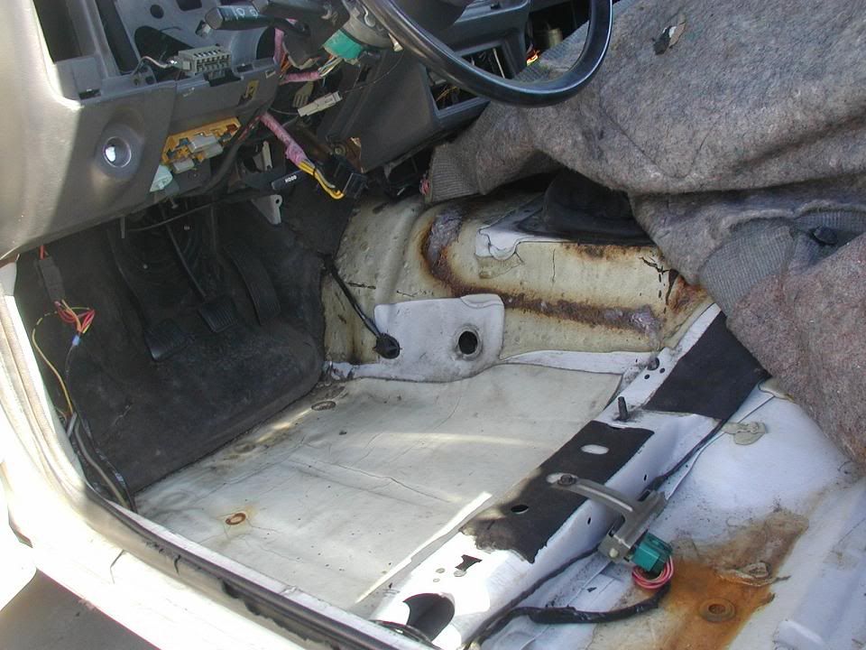
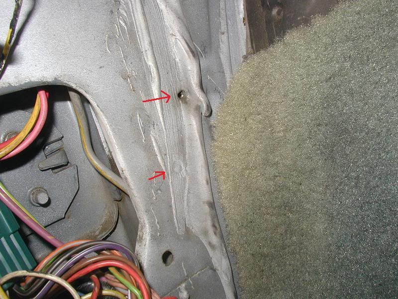
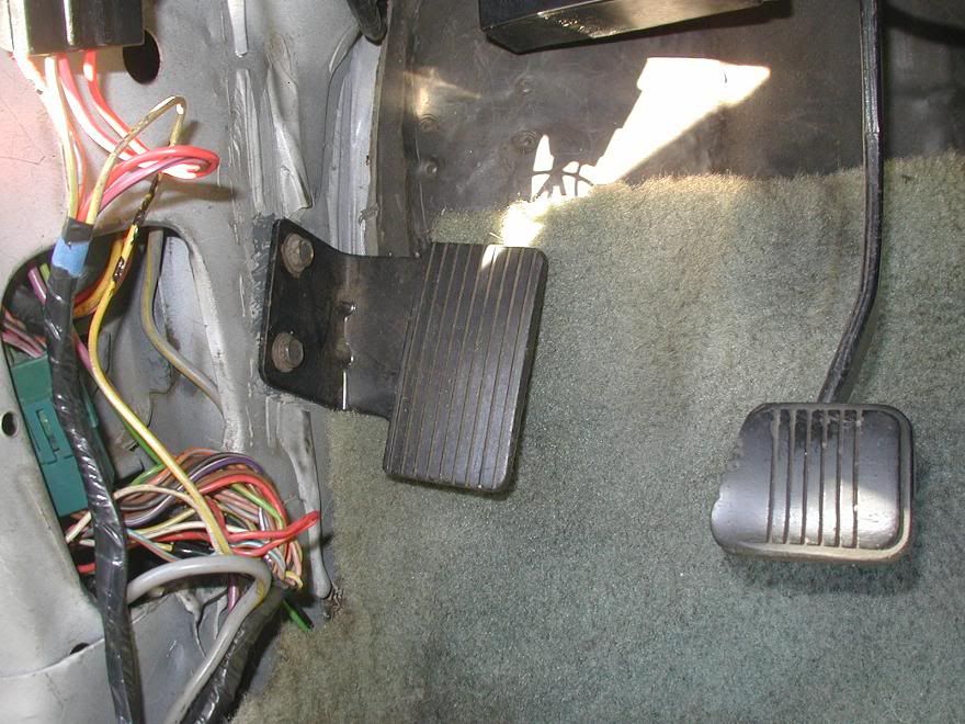
Moving back inside the car, it turns out Ford already had the holes for the dead pedal. I didn't think '84's had them. Maybe I have the SVO's to thank!
I scraped the seam sealer or what ever it was away and mounted the dead pedal - Piece-of-Cake.
I had to trim the carpet a bit since the pedal wouldn't line up with the holes otherwise.
The next few items in the engine bay I will need to drill holes for since I did not see holes or marks where they will be mounted:
BAP sensor bracket
'87 and newer Vacuum tree ('84's gets in the way of the BAP)
EGR solenoid bracket
TAD/TAB bracket.
Interestingly enough, the AC cutoff relay uses an existing screw and hole near where the old voltage regulator was mounted. I need to get the metal bracket for the AC cutoff relay.
More to follow...
Last edited by Dean_T; 02-27-2011 at 08:33 PM.
Proud owner of the one and only Friggin' Futura

Dean T,
Im sorry I missed this thread. You have done a very good job. My hat is off to you. I did a VERY similar thing to an early Fox a few years ago.
I recommend that you install a MIL/CEL in your instrument cluster. Off or on it tells you the status of the EEC at all times. The TAN wire (from the green rectancular 8 pin connector) is the lamp 'ground' that is supplied by the EEC. As Im sure you already know the EEC controls many things that are connected to a 'hot' power source and then grounded by the EEC (injectors, solenoids, FP relay, etc). The MIL/CEL is no different. Just run the TAN (from EEC pin 17) to one side of the lamp. The other side simply is connected to power with the key on.
In terms of your EEC harness I believe you have a very late 90 harness. I has a few minor wire color differences from the earlier 90 harness but it is basically the same and would plug/play in any 90. You probably know this but also be sure to use an O2 sensor harness for a manual trans car and verify the operation of your neutral gear circuit for properly signalling the EEC.
T
MF: Shoot pool Fast Eddie.
EF: Im shootin' pool Fats. When I miss you can shoot.
T,
Thank you for the info! I wasn't sure how the CEL was wired so I kepted the wiring for it in my adaper harness. I guess I need to dig out one of the spare insulated ends of the Red-Green wires I have and connect it to the other leg of a lamp socket I grabbed off a JY '85 Mustang. I think it was for the Seat Belt light but it's going to be CEL/MIL now - just need to get a Check Engine lens for my dash bezel.
In a few days Im going to post the plug configuration and pin-out of the '86, '89, '90 (late style - love to hear what your early style has), and '92-'93. I need more info to create the '91. Could also use the California '88 Mass Air information too.
(These will just be the connectors by the power brake booster, the HEGO connector, and the 8-pin Green connector) .
Dean T
Proud owner of the one and only Friggin' Futura

Just a question.. couldnt you technically grab the body harness off an 86 and just put it in? I want to do this to my 80 someday. I knew it was a big project but wow, I just read your whole thread and I must say, it is pretty involved haha.
Yes, that could be done but it won't mate up to anything other than an '86 underhood harness and '86 SEFI Speed density main wiring harness.
I wanted to use the '90 SEFI Main wiring harness I had and added the further burden of getting the wiring codes correct for '84 or 90 and I didn't want to cut and splice into the '84's wiring - weird since I ripped out all the un-needed '84 carb, alternator, charging, and emissions wiring.
There are many ways to retro fit wiring to our four eyes for SEFI, this is the method (and burden) I chose.
Now, as promised...
Proud owner of the one and only Friggin' Futura
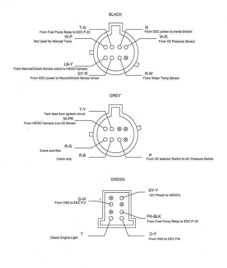
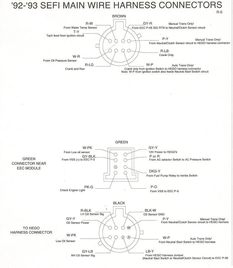
Okay, what are the gibberish I am posting now?
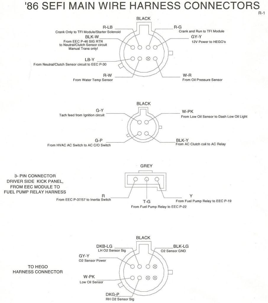
These are the pin and connector layouts of the following year SEFI Main wire harness which has the 60 pin connector for the computer.
I tried to keep the first two connectors (or one connector as the case for '91-'93 Mustangs) found near the power brake booster under the hood at the top of the page. The next connector is the 8-pin green connector found near where the EEC is mounted in the passenger kick panel (except '86 which does not have but has a 3-pin connector for the fuel pump relay circuit which is located I think over on the driver's side kick panel after entering the interior on the passenger side oval grommet).
The last connector on the bottom is the infamous connector going to the HEGO/Low Oil sensor wiring harness. All connectors shown here are as viewed looking at the main SEFI wiring harness connector. The other connectors (like the black and white 10-pin connectors and various actuators and sensors) are all common although the wire codes may vary - but the wire purpose is the same.
First, 1986!
Bonus! 1988 California ONLY Mass Air SEFI Main Harness connectors:
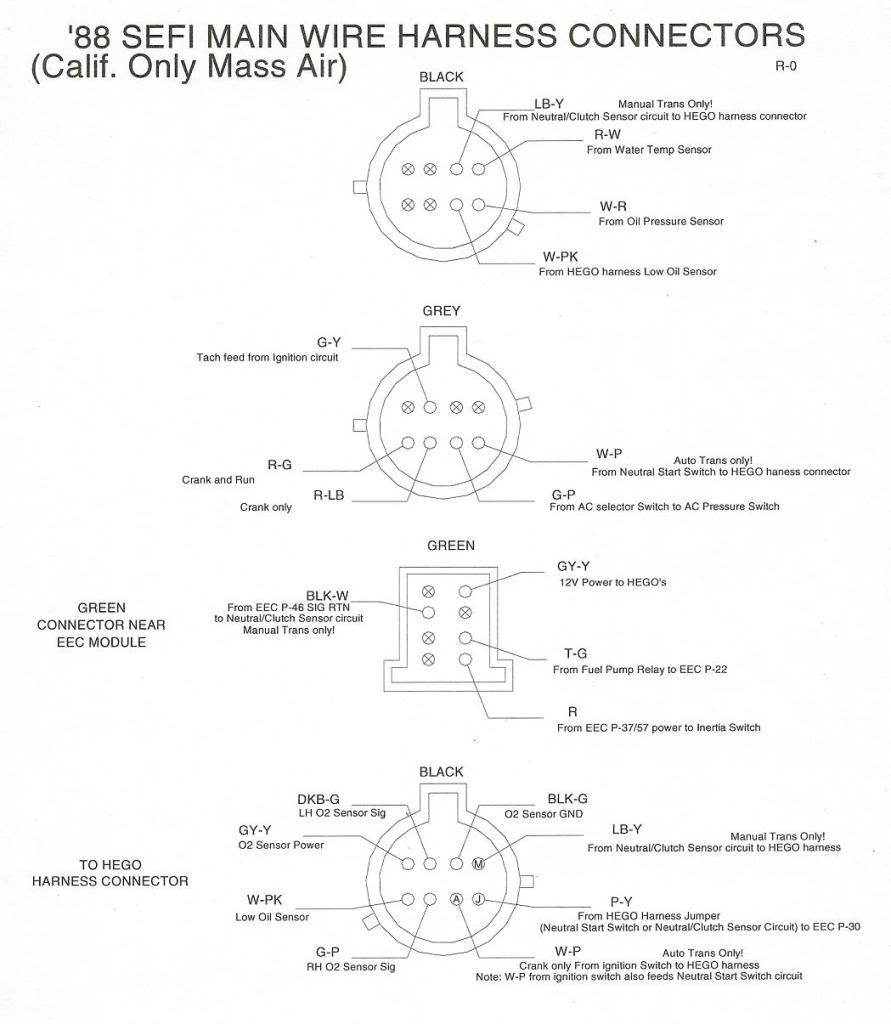
One wire I couldn't find is the one which goes between the Fuel Pump Relay to the EEC pin 19. Odd. The harness isn't mine so I can't go back and trace it.
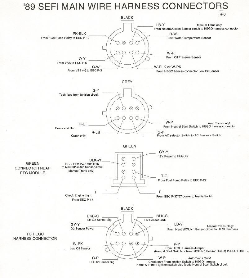
Next, 1989:
Now, 1990 (Early-patterned after the one from a '90 Mustang with a scheduled build date of 11/89)
(Too be added when I can kick my lazy scanner's @#!!)
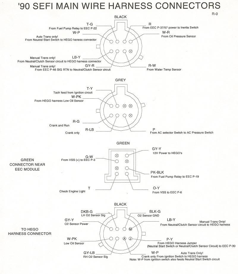
1990 (Late - patterned after the one I have grabbed first)
And last, the '92-'93:
If anyone can fill out the information for 1991, I'd like to get that info since that is the one harness I haven't been able to get my hands on.
Also, if I have errors, let me know so I can research them. The '89 may be my most sketchiest since it is still in my daily driver and I didn't want to rip it out of the car to verify where each wire goes.
Dean T
Last edited by Dean_T; 05-29-2011 at 11:39 AM.
Proud owner of the one and only Friggin' Futura
Dean, I just got a head from remembering my adding my 86 engine harness to my 84 stang to make it SEFI then doing a mass air conversion on it. Looks like your doing great. I can't wait to see it done.
84 Mustang GT, 91 roller motor,Gt40 heads, vic jr intake, quickfuel 650 carb, MSD ignition, TFS stage 1 cam, 3.73gears in 8.8, rear disc conversion, some nitrous.
 Posting Permissions

 Reply With Quote
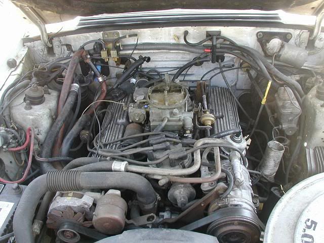


Connect With Us