Close


Page 4 of 5 FirstFirst ... 2345 LastLast
Results 76 to 100 of 114
  1. #76
    FEP Supporter
    82GTforME's Avatar
    Join Date
    Feb 2013
    Location
    Alberta, Canada
    Posts
    4,857

    Default

    Quote Originally Posted by xctasy View Post
    The US 2.8 is down 5 to 22 hp on the European 2.3, and 26 to 43 hp on the 135 hp 2.8, and for the time that the six port exhast was used on the Eurpean Granada 2.8 Injection, the US 2.8 was 51 to 70 hp down on that engine. In the first years, the 2.8 got a H-W 5200 carb to strangle it right down to make it a great economy engine in a Capri 2800. Then it got the 2150 Motorcraft in 1976, and then the illfated 2700 Motorcraft Variable Venturi. Whatever, it wasn't the cylinder heads that made the US engine a potential looser of 74% of its power, it was the cam and carburation and compression ratio. A factory 276 degree cam with 380 thou lift makes a big difference to the US cam.

    The Offenhauser is assured to increase a stock power rating 15 to 30% throught the rev range according to this. Thats 14 to 33 hp extra peak power.

    http://www.summitracing.com/int/part...97dp/overview/

    The 7% bigger Essex 3.0 UK V6 made 140 to 138 hp, with inferior flowing heads, and the same carburation as the 135 hp European 2.8. When modified with some dilligence, (and these two Cologne and Essex engines are responsive to modification, they lap it up like a 2-bbl smog 302 laps up a 4180c, headers, an intake, a cam, and a proper head that flows 15% more on itake and 30% more on exhaust. In fact, thats just with Pinto 2.0 valves, with bigger 1.75's, It would propably flow 46% more like a modified 3.0 Essex does with those valve sizes. If anything, the exhaust can stay as it is , and you could use a split lobe cam to do the rest.

    The Offenhauser intake is very badly matched for the stock intake, since it is designed for a ported head, and on its own with out head port work, the port missmatch won't make extra power. The manifold though is brilliant for creating power in all other respects.

    If a port mismatch is done with the Offy intake runners smaller than the cylinder head ports, you'll most liely get a better power result. The stock jetting of a 390 cfm 6299 part number 4150 4-bbl from Offenhausers extensive work on dyno and drag racing a 2800 engine is to go from 48 main jets to 52's. From 50 main jets to 53's, use a single stage 6.5 power valve, and open the PVCR from 21 thou to 40 thou in the primary metering block.
    Thanks for the extra info on the intake manifolds. We are going to use the stock manifold and rebuilt 2150 to start. Later on we will be installing the Offy and 4 BBL 390 CFM Holley. I am encouraged by the gains this will offer.

    Do you have the info on the stock cam for the '79 2.8? Our engine builder recommended using it as it still has a good power and RPM range. Your comments about "A factory 276 degree cam with 380 thou lift makes a big difference to the US cam" get me thinking about the differences. Where was the "factory 276 degree/0.380" lift" cam originally used? In Europe I assume.

    Hard for a non-engine guy to get the head wrapped around all of this info but I'm trying.


    Quote Originally Posted by xctasy View Post
    Those long awaited head flow figures. I knew they would be in one of my 35 boxes of Engineering manuals. From three sources.

    1. Essex V6 Stan Weiss from his World Wide Enterprises showed little illumination to the existing figures from

    2. Peter Burgess and David Gollans "How to Build, Modify & Power Tune Cylinder Heads", a Veloce Publishing PLC book first published in 1997.

    Stan W has intelligently rescaled the 25"H20 UK flow figures from this publication to suit the 28" H20 SF flow bench rating convention. Any one understanding the diffrences between US and UK flow bench certification in accordance with European and British standards will understand why there is a 5.6% uniform difference between the figures quoted on page 85 of Burgess and Gollans book. Sadly, there are no exhaust figures.

    3. The figures for the Cologne US market 2.8 are using the US flow bench, and were around all the time, I just hadn't found them again. Bill Jones from Salt Lake City, in Utah, you da man!

    Porting the US market 2.8 head is a nightmare, same as the Essex 60 degree UK engine. Both intake and exhausts are variable, thin, and easily broken into

    All measurements taken at 25"H20, with bare castings, no manifolds


    ....... Stock US (74-83)........ Modified US (74-83) .... Modified US (74-83)....|....... Stock Essex 60 UK........... Modified Essex 60 UK
    ........2.8 6 port head...........2.8 6 port head................2.8 6 port head .......|.....3.0 D port head (73-81)..3.0 D port head (73-81).
    ........ Std 1.565 " Inlet....... Ported with Stock.........Ported with Pinto 2000..|........ Std Inlet..............Ported with Pinto 2000 1.75 " Valves
    ..........................................1.565 " Inlet Vales.........1.655" Valves ...........|.....92-109 BHP SAE Net........BHP Not Tested.....BHP Not Tested........| 138 BHP DIN net 220 BHP DIN Net
    . | 110 RWHP (Manual) 175 RWHP (Manual)
    . Lift
    . (thou')
    . 50 22 24.5 27 | 19.3 23.4
    . 100 44 49 54 | 39.7 (42) 46.4 (46)
    . 150 65 72 78.5 | 60.2 69.1
    . 200 86 95 103 | 76.6 (81) 89.7 (95)
    . 250 99 109.5 116.5 | 89.2 108.4
    . 300 112 124 130 | 94.9 (100) 124 (131)
    . 350 115 127.5 132.5 | 98.7 136.8
    . 400 118 131 135 | 101.1 (107) 143.6 (152)
    . 450 | 103.2 148.7
    . 500 | 104.0 (110) 152.1 (161)

    For the exhaust:-
    -

    . Stock US (74-83) Modified US (74-83) Modified US (74-83) | Stock Essex 60 UK Modified Essex 60 UK
    . 2.8 6 port head 2.8 6 port head 2.8 6 port head | 3.0 D port head (73-81) 3.0 D port head (73-81)
    . Std 1.565 " Inlet Ported with Stock Ported with Pinto 2000 | Std Ex Valves Ported with Pinto 2000 Ex Valves
    . 1.268 " Exhaust Valves 1.417" Ex Valves |
    . 92-109 BHP SAE Net BHP Not Tested BHP Not Tested | 138 BHP DIN net 220 BHP DIN Net
    . | 110 RWHP (Manual) 175 RWHP (Manual)
    . Lift
    . (thou')
    . 50 17.5 19.5 24 | NA NA
    . 100 35 39 48 | NA NA
    . 150 50 53.5-57 (All vary) 57.5 | NA NA
    . 200 65 68-75 (All vary) 87 | NA NA
    . 250 72.5 74-80.5 (All vary) 98 | NA NA
    . 300 80 80-86 (All vary) 109 | NA NA
    . 350 82.5 82.5-88.5(All vary) 109.5-114 (All vary) | NA NA
    . 400 85 85-91 (All vary) 110-119 (all vary) | NA NA
    . 450 | NA NA
    . 500 | NA NA


    For cams, see page 15 or 56, http://www.pipercams.co.uk/pipercams..._catalogue.pdf

    For head porting, see http://speedtalk.com/forum/viewtopic.php?t=6210

    and http://www.therangerstation.com/tech...ad_porting.pdf

    For rebuilding post 1982 Euro engines, see http://faq.ford77.ru/pdf/scorpio/1245-02c.pdf
    I used the Sven Pruett book and also the guide on the Ranger Station you linked to help with my porting job. I was lucky enough not to hit any of the thin spots you mention! The flow numbers from porting alone with the stock valves are encouraging. I have never heard of this "Pinto" head you are speaking of. Can you elaborate on it? I assume it was on the "Pinto" car specifically?

  2. #77
    FEP Supporter
    82GTforME's Avatar
    Join Date
    Feb 2013
    Location
    Alberta, Canada
    Posts
    4,857

    Default

    Quote Originally Posted by 82GTforME View Post
    I still have to do the valve lash clearances and had to get the timing gears on. I had a bit of trouble getting the crank gear on. Some polishing of the shaft and gear, filing the key a hair (and a few times getting on slightly and having to use a puller to get it off 
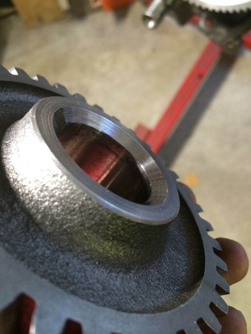
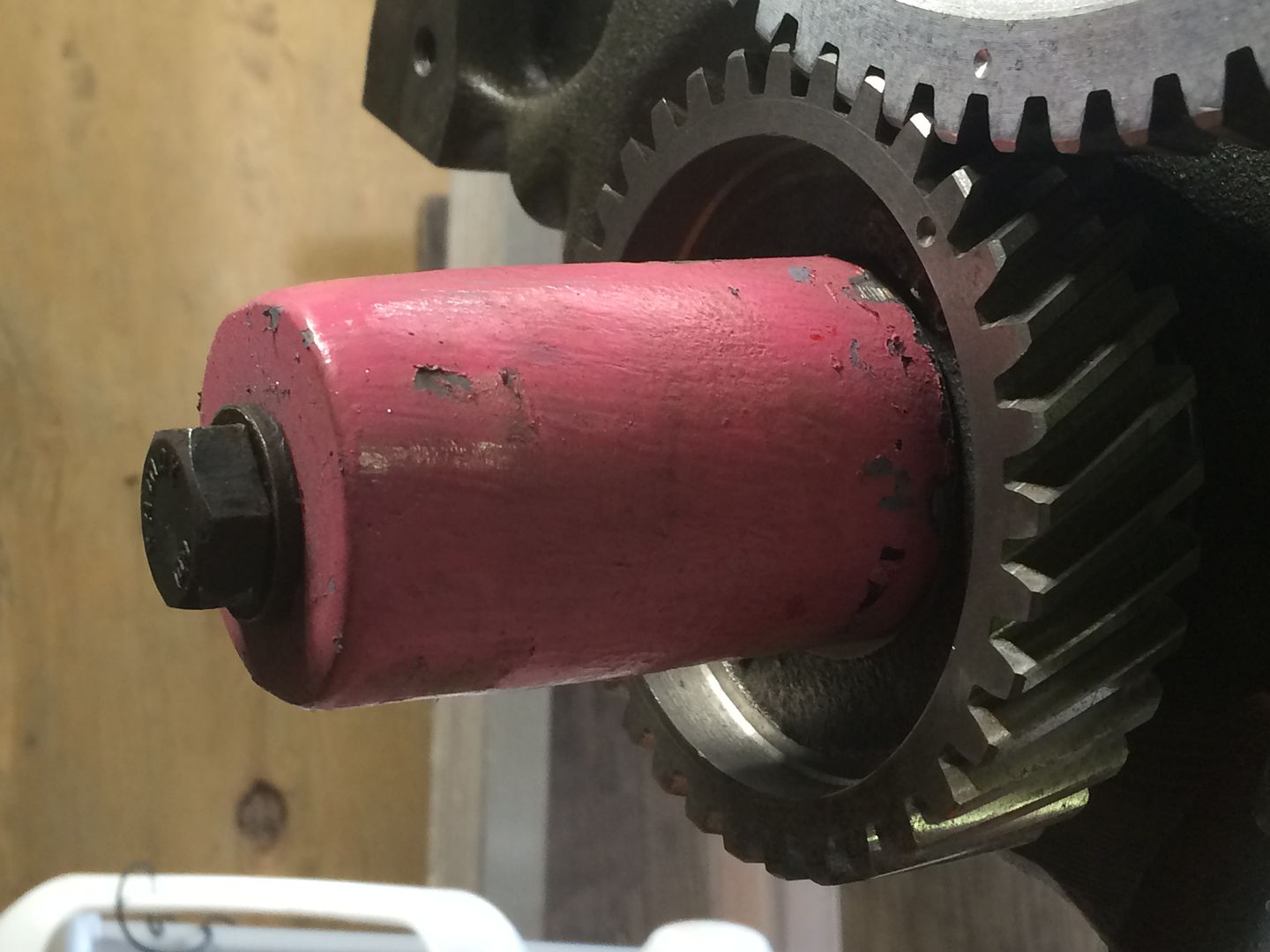
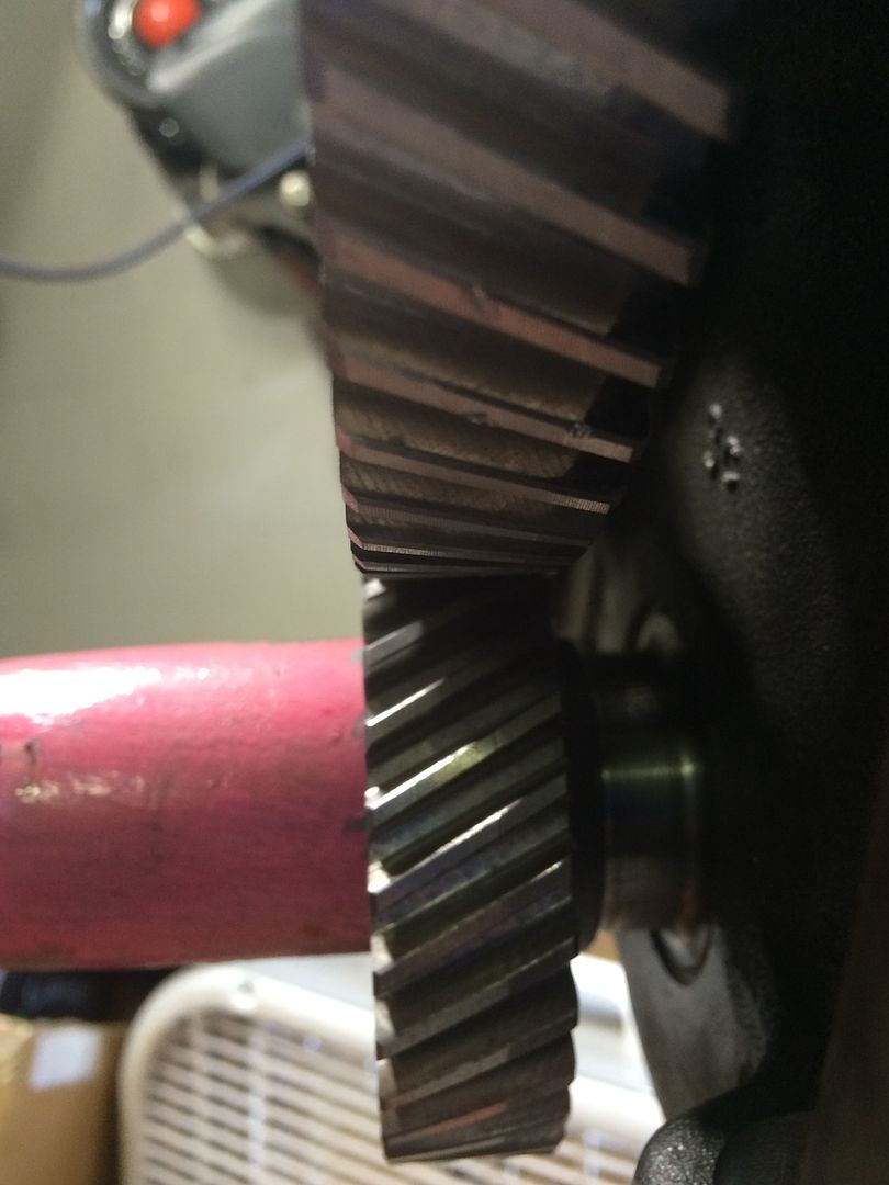
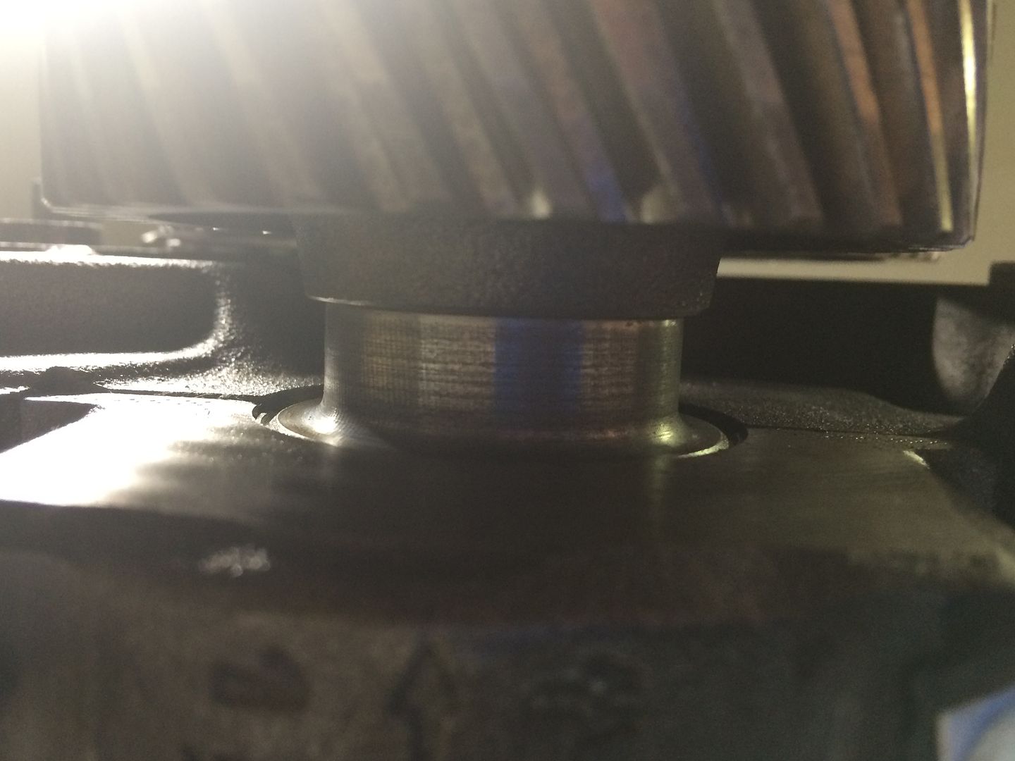
) and heating the sprocket in the oven got it on. I am not convinced it is on quite far enough although I could not, with two attempts get it on further. Everything is undamaged by sight. I am thinking when the crank pulley gets installed and torqued on it will slide the gear on if it needs to go more

    Any opinions? I think this is the first attampt putting it on and the second is (very) slightly better.


    When I get back into this after the body work, I think I am going to attempt one more install and if the results are the same, I am going to roll with this.

  3. #78
    FEP Power Member Ethyl Cat's Avatar
    Join Date
    Oct 2010
    Location
    Lebanon, IL
    Posts
    1,240

    Default

    There is a fillet on the snout of the crank. The timing gear HAS to have a chamfer on it to clear that fillet. My guess is that is is not there at all and it is preventing the gear from bottoming on the crank face.

    If it is not there, one could hand grind the clearance with a burr if actual machining processes are unavailable.

    I would not run it like that.
    BBD PERFORMANCE
    HIGH PERFORMANCE PARTS
    CUSTOM ENGINE BUILDS
    CUSTOM CAM DESIGNS
    1983 CRIMSON CAT OWNER

  4. #79
    FEP Power Member Ethyl Cat's Avatar
    Join Date
    Oct 2010
    Location
    Lebanon, IL
    Posts
    1,240

    Default

    Do not remember if this was an auto or stick, or whether you had taken measures to increase compression, but I would not run a 276 duration cam in that engine if it is pertaining to the intake lobe. The exhaust is a different story.

    I did give more of a race type cam example in an earlier post that had 270 on the intake, but I do not think you are in that realm of operation with this project.

    I would recommend something like a 254/276 224/230 .480/.390 on a 109 +7

    Should pull hard to 5000 or so and have about 200lb/ft just off idle
    BBD PERFORMANCE
    HIGH PERFORMANCE PARTS
    CUSTOM ENGINE BUILDS
    CUSTOM CAM DESIGNS
    1983 CRIMSON CAT OWNER

  5. #80
    FEP Supporter
    82GTforME's Avatar
    Join Date
    Feb 2013
    Location
    Alberta, Canada
    Posts
    4,857

    Default

    Quote Originally Posted by Ethyl Cat View Post
    There is a fillet on the snout of the crank. The timing gear HAS to have a chamfer on it to clear that fillet. My guess is that is is not there at all and it is preventing the gear from bottoming on the crank face.

    If it is not there, one could hand grind the clearance with a burr if actual machining processes are unavailable.

    I would not run it like that.
    The gear had the chamfer as well. I know I'll look into it more once I get back onto the engine portion of my resto. My nature won't have me leave it.

    Quote Originally Posted by Ethyl Cat View Post
    Do not remember if this was an auto or stick, or whether you had taken measures to increase compression, but I would not run a 276 duration cam in that engine if it is pertaining to the intake lobe. The exhaust is a different story.

    I did give more of a race type cam example in an earlier post that had 270 on the intake, but I do not think you are in that realm of operation with this project.

    I would recommend something like a 254/276 224/230 .480/.390 on a 109 +7

    Should pull hard to 5000 or so and have about 200lb/ft just off idle
    It is an auto C3 right now but we hope to get an SROD in it one day. We are going with the stock camshaft to save money on this build. Valve job, decent porting job now. Offy and four barrel in the future. I will address a different camshaft then. I know we've made improvements with flow, the rest will come later. I'll note the Cam recommendation Steve. Would that recommendation change with the Offy or manual/auto? We're not building a race car by any means but want to get what we can.

  6. #81
    FEP Super Member xctasy's Avatar
    Join Date
    Jun 2012
    Location
    Dunedin 9011, New Zealand, South Pacific
    Posts
    3,961

    Default

    Quote Originally Posted by 82GTforME View Post
    Where was the "factory 276 degree/0.380" lift" cam originally used? In Europe I assume.


    Hard for a non-engine guy to get the head wrapped around all of this info but I'm trying.


    I used the Sven Pruett book and also the guide on the Ranger Station you linked to help with my porting job. I was lucky enough not to hit any of the thin spots you mention! The flow numbers from porting alone with the stock valves are encouraging. I have never heard of this "Pinto" head you are speaking of. Can you elaborate on it? I assume it was on the "Pinto" car specifically?
    Yep, the 276 cam is the standard 150 to 160 hp fuel injection camshaft, and it gave great power, with reasonable torque. Its a typical German cam though, lots of top end, loose torque at the low end.

    The Pinto 2000 is the standadr 1971 to 1974 Pinto/Capri 2000 cc intake and exhaust valve. The can be fitted to the US 2.8 V6 with a 3 angle valve grind, some throat work, and by cutting the valve down 50 thou, and gently heating the tip to a cheary red with an oxy torch. There are also Power Pac 2000 Pinto valves which are aftermarket, and even bigger. Each fit.


    Ethyl Cat, I knew you'd find a better cam profile based on the cfm head flow. The figures confirm what I've said, I just couldn't find them, but I knew I'd seen them in 2007, and it so bugged me. Sorry its taken so long. I'm sure the Offy intake will be as efficent as the Pinto 2000 2-bbl was, a 10% drop in peak cfm, and port to port balance in cfm within 1 or 2% of each other if its matched to the ports right.

    If you dig, you find Ford engines have excellent data, which allow you to really work them hard. Scientifically.! The advice you have given is pretty much bang on.

    My little 114 hp Cortina did an indicated 118 mph in a Mustang sized car with a 0.42 drag factor, 20.3 sq foot frontal area, and just a 34 Solex 2-bbl, Duraspark, and 3.45:1 axle and C3 with the 2.2 stall ratio converter. It had stock headers and a low restriction 2.125" exhasut. And the stock European camshaft.

    Both the 102 hp net 2000 German Pinto engine and 2.8 German market 135 to 150/160 hp engines were all over cammed, with poor low speed torque due to the durations figures with both valves 30 thou open, and the lobe centers and high peak duration. The valves on the Cologne only lift a 1.47 ratios, and what is needed is a good American style cam with the right lobe centers to match higher compression . When you reduce intake duration, you gain torque and low end tractability. Like the Pinto 2000, the US 2800 has supprisngly good air flow but the US 2.8 is mising port area, and compression, and camshaft duration. The Pinto had too much port area, and bad short turn radius. The US Colgne head was well designed, but my goodness its rough, and needs a good de-dag and some better valves. To raise compression, you deck the head, and cut back the manifold. Or go to the European pistons.

    With that info, it just confirms your inital thoughts.


    This US engine doesn't diserve the anti 6 port head crap dished out to it by the Sunbeam forums and others, they are unformed. I would love to know the exhaust flow figgures of the German 2.3, 2.6 and 2.8 5 port heads, the Essex 2.5/3.0 or its 1.7/2.0 V4 variants, the Saab 96 V4 would be similar.


    All that info is around, and the siamese exhaust ports were probably a good solution. Ford USA requested a change of the ages old 62-73 V4 exhaust for the 2.8 US market engine for some reason, and the little US 2.8 lookes like a great base if the grinder doesn't break through the casting.

  7. #82
    FEP Power Member Ethyl Cat's Avatar
    Join Date
    Oct 2010
    Location
    Lebanon, IL
    Posts
    1,240

    Default

    [QUOTE=82GTforME;1705014]The gear had the chamfer as well. I know I'll look into it more once I get back onto the engine portion of my resto. My nature won't have me leave it.

    Make sure it is deep enough!

    I probably would not change based on your intentions
    BBD PERFORMANCE
    HIGH PERFORMANCE PARTS
    CUSTOM ENGINE BUILDS
    CUSTOM CAM DESIGNS
    1983 CRIMSON CAT OWNER

  8. #83
    FEP Supporter
    82GTforME's Avatar
    Join Date
    Feb 2013
    Location
    Alberta, Canada
    Posts
    4,857

    Default

    Thanks for all of the insight Xctasy. Always interesting information to read. Plus so far so good with the grinder!

    Steve, thanks too!

  9. #84

    Default

    hi 82gtme, i sent you a PM incase you are wondering where that came from in your inbox.

  10. #85
    FEP Supporter
    82GTforME's Avatar
    Join Date
    Feb 2013
    Location
    Alberta, Canada
    Posts
    4,857

    Default

    Quote Originally Posted by 82GTforME View Post
    I know I'll look into it more once I get back onto the engine portion of my resto. My nature won't have me leave it.


    I took another look at this finally.

    I picked up a Comp Cam gear set which has an aluminum cam gear compared to the plastic-like toothed factory gear.


    In the instructions, it mentioned two types of installs. One had a spacer as part of the gear and one had a seperate spacer. It got me thinking as to whether I lost, misplaced or forgot to install a spacer between the plate and the gear. I looked at the 79 Ford parts book and it does not show a spacer there.

    Was thinking the left pic would be my application, but now I'm not so sure:


    I'm thinking my install method isn't perfect or good enough. I've read about using a tool to drift it on a little harder than I am attampting to. Maybe I'm afraid to hit it too hard 
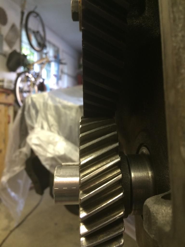
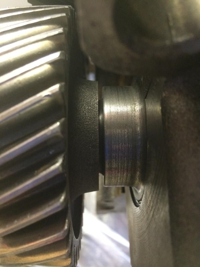
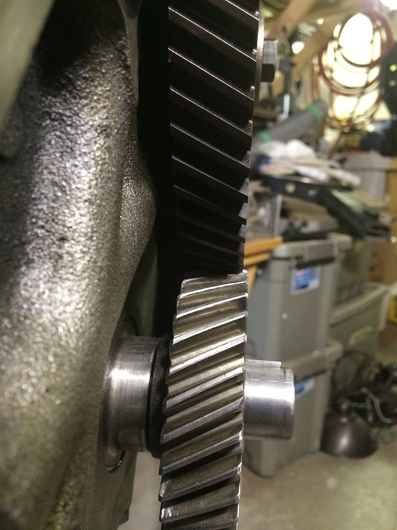
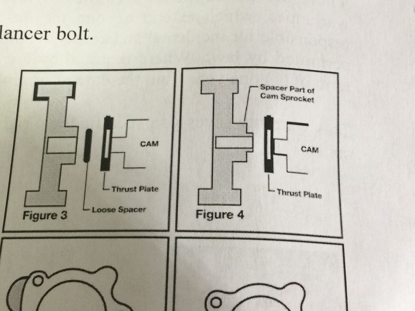
I'm thinking a piece of steel pipe or something that fits over the crank snout would work for even pressure.


    That or make a press similar to the one available for purchase.


  11. #86
    FEP Supporter
    82GTforME's Avatar
    Join Date
    Feb 2013
    Location
    Alberta, Canada
    Posts
    4,857

    Default

    Success!

    Correct chamfer.


    Homemade press.


    It just needed that little bit of help and voila.


  12. #87
    FEP Supporter
    82GTforME's Avatar
    Join Date
    Feb 2013
    Location
    Alberta, Canada
    Posts
    4,857

    Default

    Quote Originally Posted by 80Notch View Post
    have a shop run a nice dual exhaust like the later LX style with flowmasters...it will have a decent little rumble and a tad bit more balls than stock
    Quote Originally Posted by Zap's 85 GT View Post
    Some better exhaust cant hurt either.
    Quote Originally Posted by xctasy View Post


    I'd keep the cast headers as they are, they are very efficient, and just add a dual exhast. There is a sensational Offenhauser 4-bbl intake which takes a vac sec 390 Holley 4-bbl, and that is a very strong set up.
    Quote Originally Posted by Fordhorsemen View Post
    Run Dual exhaust from stock manifolds Back & will give you a Good Lil Gain.
    So I picked up a 2.5" BBK H-pipe with Flowmaster mufflers and tail pipes locally that are like new. I have a few options for vehicles to put this on but I am thinking it may work for this car. The current collector on the wye is 2.25" so this would be quite a bit bigger. Is there a detriment to having this big of a system with this V6? We will be going with the Offy 4 bbl eventually so we could grow into it I suppose.

  13. #88
    FEP Super Member xctasy's Avatar
    Join Date
    Jun 2012
    Location
    Dunedin 9011, New Zealand, South Pacific
    Posts
    3,961

    Default

    I'd already built up a bad a$$ 4.1 liter propane six in 1997. I used a single 1.875" exhaust

    I spent about a year researching the Cologne V6.

    In that capacity of six cylinder engine, Brisbane Engine guru and Holden 138/179/186/202 cubic inch racer Dick Johnson said on six cylinder or v8 engines, ensuring there is discharge flow velocity is important. The David Vizard tech articles backed this up as the exhaust being the 4 stroke Otto engines "5th stroke". The tail pipes aren't where the power is gained or lost, its the 30 inches from the header to the collector. In dyno programs, that's what they look at.

    In 2000, I followed the European 188 hp Turbo 2800 cc engine detail, but used a smaller IHI Mazda 626/Ford Probe Turbocharger (what Chev used in the 660 Turbo Citation project car in 1981), and fueled it with an Aber adaptor to fit a V8 designed 207 hp Impco carb. It fed to the stock European/German market Taunus/Cortina 2300 V6, a 114 hp engine very much like the old 2600, but with Fords European Bosch Duraspark and a Solex 34 2-bbl carb which was direct mount, not staged. I had two engines, an early blue German 2.8, and the later German 2.3. I used the 2.3 since it could rev to 7000 rpm or more without the Duraspark tripping out, and did 118 mph at 5900 rpm with just the old C3 auto, 3.45 axle gears, and the exhaust modification alone, a stock engine in a Mustang sized car doing that was pretty good.


    Even the siamesed V4 exhaust that all those V6's ran from 1967 till 1985 were efficient. If they weren't, the Germans wouldn't have used a V4 exhaust for 18 years, especially when they had tooled up for the US 2.8 heads when the Weslake Fuel injection engine came out.


    Indications are that ideal exhaust size has to be a little similar to gain flow motion at the exhaust. I used a 2" single from the Aussie Cortina six in line, and the results were fantastic. Sound was good, power expectional.

    Basically, somewhere in the system, you have to increase the speed of the spent gas from what it would be with two 2.25" pipes right through. You do that by engine analyser programs. Ethyls recomendatios were in line with that.

    Gas speed needs to be able to drag the other exhaust pulses out, sort of a net positive suction head situtation, where the discharging, fast cooling and yet expanding and more rarified gas is discharging into a cold sedentry enviroment.

    See the previous two posts. I trust and engine builder with some engine analysing experience.

    http://vb.foureyedpride.com/showthre...-options/page2
    Quote Originally Posted by Ethyl Cat View Post
    Not anything near EASY, but this thread got me thinking what I would do if I were to build one of these engines on a realtively tight $$ budget. Sooo, after about 5 hrs of research tonight(hard to find info on these things) this is what I have. Maybe someone will be interested maybe not.

    1. Bore to 3.680 and install Ford 255(4.2L) v8 pistons. You have to bore the pin bores out to fit the .945 pin but you gain something valuable.
    a. From what I can find the 2.8 piston is .060 in the hole creating a ground pounding 8.7:1 compression ratio. Piston compression height is 1.535. The 4.2 piston has a compression height of 1.585, placing the top a mere .009" from the deck. This raises compression to 9.5:1. Yah!

    2. Next I would source some Toyota 3TC intake valves to gain a little cross section to spin about 6500 rpm size= 1.615". most likely would run 22r retainers and locks.
    The exhaust looks to be a 4.0 v-6 ford piece 1.358" in diameter and will run stock locks and retainers. Valve springs for both applications are very similar with the 22r spring getting the nod(better pressures at the same installed heights) if the Ford head will accept a slightly smaller spring ID. Otherwise I'm sure there are drop in performance springs for both.

    3. After the valve job, port work would be performed to increase airflow.

    4. Contrary to popular belief, I would run headers, but of my own design, keeping primary pipes small and relatively long (30+inches) with a 2.125-2.250" collector

    5.Flow numbers are really hard to come by for these engines (so far) so a cam is tricky right now.Preliminary thoughts are 270/280 230/230 .472/.450 net lift 110lsa 102 ICL STICK SHIFT ONLY. This cam will not work too well without a stall converter in your C3. Automatics would get a different profile.

    This cam has better low rpm cylinder pressure potential than the larger of the 3 comps and more exh seat to seat due to the TERRIBLE exhaust ports
    55 degrees overlap should be ok for power brakes (close).

    My intake lobe seems bigger than the biggest of the Comps until you see that the advertised duration is at .020" valve lift. This one is at .006"

    6. Not sure about induction. I have never seen an intake yet. My first instinct would be a 500 Holley 2bbl though.

    Well there it is, my hypothetical 2.8 engine. Doesn't it sound nice? I am sure it will make 250hp here on the internet!

    The numbers add up , but I have never built one of these engines. ( I would though!!)

    Also OP there are some pretty good grinds for your engine at http://catalog.elginind.com/app/Engi...gh+Performance

    They can be had for less than the Comp stuff as well.

    Now I can sleep!

    Steve
    Quote Originally Posted by Ethyl Cat View Post
    Do not remember if this was an auto or stick, or whether you had taken measures to increase compression, but I would not run a 276 duration cam in that engine if it is pertaining to the intake lobe. The exhaust is a different story.

    I did give more of a race type cam example in an earlier post that had 270 on the intake, but I do not think you are in that realm of operation with this project.

    I would recommend something like a 254/276 224/230 .480/.390 on a 109 +7

    Should pull hard to 5000 or so and have about 200lb/ft just off idle
    You might get away with those 2.5 outlets if the pipes are 30 inches long to the 2.25" collectors

  14. #89
    FEP Power Member Ethyl Cat's Avatar
    Join Date
    Oct 2010
    Location
    Lebanon, IL
    Posts
    1,240

    Default

    1 5/16 header pipes 33 inches long with no bigger than a 2" collector.
    BBD PERFORMANCE
    HIGH PERFORMANCE PARTS
    CUSTOM ENGINE BUILDS
    CUSTOM CAM DESIGNS
    1983 CRIMSON CAT OWNER

  15. #90
    FEP Supporter
    82GTforME's Avatar
    Join Date
    Feb 2013
    Location
    Alberta, Canada
    Posts
    4,857

    Default

    Quote Originally Posted by xctasy View Post
    You might get away with those 2.5 outlets if the pipes are 30 inches long to the 2.25" collectors
    Quote Originally Posted by Ethyl Cat View Post
    1 5/16 header pipes 33 inches long with no bigger than a 2" collector.
    ID of the factory exhaust manifolds are 1.5" which joined into the factory wye "collector" at 2.25".

    After reading your comments, I'm wondering if I were to maintain the manifold outlet size of 1.5" from each side for the "33 inches" which should maintain the velocity until it were to hit the proposed 2.5" H-pipe. If I have to modify the H-pipe (shorten the inlet side) I'm good with that. BTW, we are not going to be using a catalytic convertor if we go with the duals.

    If the 2.5" is going to be too big, the only other way to get the smaller diameter pipes would be a custom set-up which would be out of the budget scope at this point. The price was right on the 2.5".
    Last edited by 82GTforME; 08-27-2015 at 11:04 PM. Reason: Grammar baby!

  16. #91
    FEP Super Member xctasy's Avatar
    Join Date
    Jun 2012
    Location
    Dunedin 9011, New Zealand, South Pacific
    Posts
    3,961

    Default

    Steve's sizing is the critical point. Power is made in the first 33 inches, it won't be lost in the last 45 inches if they are too big.

    He has access to other means for calculating ideal pipe sizes. After that, I think he's looked at 2-1/8 to 2-1/4" as ideal, but you can insert or restrict with flanges that are 2-1/8 or 2-1-4". It would then still be a no loss system.

    Some car makers, like Mitsubishis Starion and Cordia turbos with the Silent Shaft Sirius based 1995 and 1796 cc engines in Australia 1985-1986, restricted the exhaust right at the flange after doing bizzion dollars of carful flow testing up and downstream. That was to premote cold catalyst light off, and bring the turbo on boost ealier. So you'll find engieers have ideal recommendations, but if the parts are already in the system and on the car, what next can you do? Set up an internal restriction!


    So basically, if you've got 2-1/2"'s cheap, then look at any other flange that it may have, and neck it down in side at that point.It will set up a flow dam, which will reduce mixture motion. Make sure its no a settling point at the base, but you can certainly restrict at intenal flange points. MMCL did that plenty of times. Plenty of us use 2.5" pipes going over the tail to restrictve 2-1/2" outlets, so as long as the first 33 inches are close to that, you'll be fine.


    Even looking at the old European 188 hp Capri turbo, which has the same basic bottom end as your 2.8 Mustang, it had twin pipes with V4 headers and some really restrictive exhaust attachments. Going big after basically 33" of 1-1/2" pipe, you'd be doing better than the factory system.


  17. #92
    FEP Power Member Ethyl Cat's Avatar
    Join Date
    Oct 2010
    Location
    Lebanon, IL
    Posts
    1,240

    Default

    That 33" is single cylinder single tube length. Also the pipe size is OD

    If running stock manifolds we can cross are fingers and hope that the runners are about 15" long.

    If possible open the manifold outlet up to 1.75" and run 1.75" pipe for 36 inches as the "collector".

    Place the H pipe at the 36" mark if you are running duals or you could run the 1.75 together into the 2.5 stuff you have and run a single exhaust.

    Ideal and what will usually fit under the car are normally not in agreeance with each other. See what you think you can do and we will find a good compromise.
    BBD PERFORMANCE
    HIGH PERFORMANCE PARTS
    CUSTOM ENGINE BUILDS
    CUSTOM CAM DESIGNS
    1983 CRIMSON CAT OWNER

  18. #93
    FEP Supporter
    82GTforME's Avatar
    Join Date
    Feb 2013
    Location
    Alberta, Canada
    Posts
    4,857

    Default

    Quote Originally Posted by Ethyl Cat View Post
    That 33" is single cylinder single tube length. Also the pipe size is OD

    If running stock manifolds we can cross are fingers and hope that the runners are about 15" long.

    If possible open the manifold outlet up to 1.75" and run 1.75" pipe for 36 inches as the "collector".

    Place the H pipe at the 36" mark if you are running duals or you could run the 1.75 together into the 2.5 stuff you have and run a single exhaust.

    Ideal and what will usually fit under the car are normally not in agreeance with each other. See what you think you can do and we will find a good compromise.
    Thanks for the info Steve! I think the 2.5" will fit no problem in this car (especially with the upgraded dual hump now).

    In this crude picture, I'm assuming the factory flange location going into the catalytic convertor would be close to the mid-pipe start location or close to it. That would give approximately 24" of 1.75" pipe. Is the location of the H critical?


    Quote Originally Posted by xctasy View Post
    So basically, if you've got 2-1/2"'s cheap, then look at any other flange that it may have, and neck it down in side at that point.It will set up a flow dam, which will reduce mixture motion. Make sure its no a settling point at the base, but you can certainly restrict at intenal flange points. MMCL did that plenty of times. Plenty of us use 2.5" pipes going over the tail to restrictve 2-1/2" outlets, so as long as the first 33 inches are close to that, you'll be fine.
    If the above 24" +/- a few arent enough maye the restriction could be downstream of the H?
    Last edited by 82GTforME; 02-11-2016 at 10:53 PM.

  19. #94
    FEP Power Member Ethyl Cat's Avatar
    Join Date
    Oct 2010
    Location
    Lebanon, IL
    Posts
    1,240

    Default

    Yes the location makes a difference
    BBD PERFORMANCE
    HIGH PERFORMANCE PARTS
    CUSTOM ENGINE BUILDS
    CUSTOM CAM DESIGNS
    1983 CRIMSON CAT OWNER

  20. #95
    FEP Supporter
    82GTforME's Avatar
    Join Date
    Feb 2013
    Location
    Alberta, Canada
    Posts
    4,857

    Default

    Quote Originally Posted by Ethyl Cat View Post
    If possible open the manifold outlet up to 1.75" and run 1.75" pipe for 36 inches as the "collector".

    Place the H pipe at the 36" mark if you are running duals..
    Quote Originally Posted by Ethyl Cat View Post
    Yes the location makes a difference
    I think my plan if we go with this is to run the 1.75" for the collector as you suggest and run it into the 2.5" pipes I purchased. To clarify, where is the 36" mark you are talking about for the H pipe measured from Steve? Is it from the exhaust outlet on the head or manifold or from the end of the collector?

    Thanks!

  21. #96
    FEP Power Member Ethyl Cat's Avatar
    Join Date
    Oct 2010
    Location
    Lebanon, IL
    Posts
    1,240

    Default

    Quote Originally Posted by 82GTforME View Post
    I think my plan if we go with this is to run the 1.75" for the collector as you suggest and run it into the 2.5" pipes I purchased. To clarify, where is the 36" mark you are talking about for the H pipe measured from Steve? Is it from the exhaust outlet on the head or manifold or from the end of the collector?

    Thanks!
    From the manifold outlet
    BBD PERFORMANCE
    HIGH PERFORMANCE PARTS
    CUSTOM ENGINE BUILDS
    CUSTOM CAM DESIGNS
    1983 CRIMSON CAT OWNER

  22. #97
    FEP Supporter
    82GTforME's Avatar
    Join Date
    Feb 2013
    Location
    Alberta, Canada
    Posts
    4,857

    Default

    Quote Originally Posted by xctasy View Post
    Steve's sizing is the critical point. Power is made in the first 33 inches, it won't be lost in the last 45 inches if they are too big.
    Quote Originally Posted by Ethyl Cat View Post
    From the manifold outlet

    Got thinking about this exhaust system again and wanted to share the start-up for you.

    I will be coming back here for more questions soon to tune it properly.

    You guys have helped me a lot up to now. Thanks!


  23. #98
    FEP Supporter
    82GTforME's Avatar
    Join Date
    Feb 2013
    Location
    Alberta, Canada
    Posts
    4,857

    Default

    Quote Originally Posted by Ethyl Cat View Post
    If running stock manifolds we can cross are fingers and hope that the runners are about 15" long...
    If possible open the manifold outlet up to 1.75" and run 1.75" pipe for 36 inches as the "collector"....
    Place the H pipe at the 36" mark if you are running duals...
    Ideal and what will usually fit under the car are normally not in agreeance with each other.
    Quote Originally Posted by xctasy View Post
    I spent about a year researching the Cologne V6...

    Indications are that ideal exhaust size has to be a little similar to gain flow motion at the exhaust...

    Ethyls recomendatios were in line with that...

    Gas speed needs to be able to drag the other exhaust pulses out, sort of a net positive suction head situtation, where the discharging, fast cooling and yet expanding and more rarified gas is discharging into a cold sedentry enviroment...

    You might get away with those 2.5 outlets if the pipes are 30 inches long to the 2.25" collectors
    Quote Originally Posted by xctasy View Post
    Steve's sizing is the critical point. Power is made in the first 33 inches, it won't be lost in the last 45 inches if they are too big.

    He has access to other means for calculating ideal pipe sizes. After that, I think he's looked at 2-1/8 to 2-1/4" as ideal, but you can insert or restrict with flanges that are 2-1/8 or 2-1-4". It would then still be a no loss system.

    So basically, if you've got 2-1/2"'s cheap, then look at any other flange that it may have, and neck it down in side at that point.It will set up a flow dam, which will reduce mixture motion. Make sure its no a settling point at the base, but you can certainly restrict at intenal flange points. MMCL did that plenty of times. Plenty of us use 2.5" pipes going over the tail to restrictve 2-1/2" outlets, so as long as the first 33 inches are close to that, you'll be fine.
    I know it's been a while since this was discussed but I wanted to update you with where I have gotten to.

    Quote Originally Posted by Ethyl Cat View Post
    Ideal and what will usually fit under the car are normally not in agreeance with each other. See what you think you can do and we will find a good compromise.
    After installation, these are the dimensions I roughtly measured.

    Exhaust manifold on the D side is only 9" from number 4 cylinder to the outlet. The 1-3/4 is 28" to where it up sizes and enters the 2.5" system. The H is about 25" beyond that which is around 53" total from the manifold outlet. A big difference from the 36" you had originally recommended. Down stream of the H are the first flanges and the only opportunity I have to put in some sort of restrictor as xctasy suggested.

    Do you think it would be good to maintain the 1-3/4 collector size? The sound is not too bad especially at idle or under light to medium acceleration. Once the RPM's get up there it does get a little (to me) dronish and little ricey. It is good but I would like to ensure proper exhaust flow.

    Thanks for all of your help!!


  24. #99
    FEP Power Member Ethyl Cat's Avatar
    Join Date
    Oct 2010
    Location
    Lebanon, IL
    Posts
    1,240

    Default

    Nice!
    BBD PERFORMANCE
    HIGH PERFORMANCE PARTS
    CUSTOM ENGINE BUILDS
    CUSTOM CAM DESIGNS
    1983 CRIMSON CAT OWNER

  25. #100
    FEP Super Member xctasy's Avatar
    Join Date
    Jun 2012
    Location
    Dunedin 9011, New Zealand, South Pacific
    Posts
    3,961

    Default

    Quote Originally Posted by Ethyl Cat View Post
    Nice!
    And from me also....nice!

    EB|< 331 is a fine piece of Orange Crush.

    In England with the 2.5 and 3.0 liter Essex 60 degree V6 (Zephyr MKIV/Granada Mk I, Capri 3000 GXL/GT and "S" 1959-1981), and the world over with the 2300, 2600, 2800, 2900, and 4 liter Cologne V6, Ford created the aggressive, hard edged staccato growl which the likes of Datsun (L24/26/28, VG30E) and BMW (the small bore and large bore in line sixes, but especially BMW M20 engine, which was used n Diesel form in L code Hash 7 Lincoln Continentals and LSC's. If you filter out the diesel knock, you get the same German mid range from any Colgne V6 as the M20's, gasoline or diesel.

    https://www.youtube.com/watch?v=g0jC16j7gsg


    In the same way a turbo absorbs the noise, so too do resonators, cataysts, and mufflers. Just addeding some used cataysts (AS LONG AS THE HAVE HEAT SHEILDS FITTED FOR SAFETY) won't hurt power, or sound.


    My English 2.3 1982 Cortina Ghia V6 with Mustang/Bronco II C5 auto had a dual exhaust system before its single twin system, and despite the lack of 1/2 liter of capacity and two extra branches to the manifolds on each side, it has the same Germanic hard edge. Its very similar to the 4.0 Explorer. With a large 1-7/8" Australian TE 4.1 Cortina 6 exhaust, the drone was aggressive, but very rauchy. Going to the twin 1-3/4" pipes softened the drone, and added some higher pitched fun to city and highway drives. Adding two resonators and two mufflers right at the back is the best you can do for flow velocity and sound condidtiong...it then softened the sound even more, so you could pick up a really nice, 1981 BMW 323i sound.

    Stock size

    https://www.youtube.com/watch?v=f4zk4krJF0k


    Larger tuber sizes, dual verses single

    https://www.youtube.com/watch?v=UBivq9Y-vHw


    Larger tuber sizes, dual
    https://www.youtube.com/watch?v=JPHG_6iy3iM

    When you add a small tail pipe to the Mustang, even like my 3.3 1981, the drone is not the tail pipes, but the mid wind section of the orchestra. So you need to focus on that.


    What Ford did on the 4.0 was invest in a non mandrel bent exhaust with iron headers, but down pipes which were thick wall and well formed. The latter part of a Cologne V6 exhaust is always a gaint tuning fork which has a reverb function to it that induces a drone.

Page 4 of 5 FirstFirst ... 2345 LastLast

Posting Permissions

  • You may not post new threads
  • You may not post replies
  • You may not post attachments
  • You may not edit your posts
  •