
Hey, I have not been able to locate a harness for my alternator and was wondering if anyone knows how to wiring up a 1g alternator...I am not in a position to upgrade to the 3g which is better.
So I really needs some help here.


Hey, I have not been able to locate a harness for my alternator and was wondering if anyone knows how to wiring up a 1g alternator...I am not in a position to upgrade to the 3g which is better.
So I really needs some help here.


The alternator wiring is pretty simple. The "BAT" terminal is pretty obvious, as is
the "GND" terminal. The only other thing you need for the alternator to charge is
to connect the "FLD" terminal to the "F" terminal on the regulator. If you have
a Motorcraft carburetor, the "STA" terminal connects to the electric choke cap.
Otherwise it doesn't connect to anything.
Cheers,
Jeff Cook
'85 GT Hatch, 5-speed T-Top, Eibachs, Konis, & ARE 5-Spokes ... '85 GT Vert, CFI/AOD, all factory...
'79 Fairmont StaWag, 5.0, 62K original miles ... '04 Azure Blue 40th Anny Mach 1, 37K original miles...
2012 F150 S-Crew 4x4 5.0 "Blue Coyote"... 65 coupe, 289 auto, Pony interior ... '67 coupe 6-cyl 4-speed ...
'68 Vert, Mexican block 307 4-speed... '71 Datsun 510 ...
And a 1-of-328 Deep Blue Pearl 2003 Marauder 4.6 DOHC, J-Mod, 4.10s and Lidio tune

JACook,Originally Posted by JACook

I usually agree with your advice but on this one Im pretty sure that he will need more than only the FLD connection between the alternator and the regulator.
This diagram shows a Ford 1G alternator and external regulator wiring circuit:
http://fordfuelinjection.com/public/...ALT_wiring.gif
However this is for a system that used a charge indicator lamp. The 79-86 Mustangs with the ammeter circuit is slightly different. I havent found a good online diagram but on the ammeter circuit the switched 12V goes directly to the S (stator) terminal on the regulator. No connection is made at the I (indicator) terminal on the regulator. The only connection on the STA terminal on the alternator would be the electric choke (if needed).
Summary for wiring with ammeter (Mustang):
Alternator
B (output stud) - to battery + at starter relay (w/ fuse link)
STA - to electric choke (if required)
FLD - to F terminal on regulator
GND - to ground
Regulator
I - not used in ammeter (Mustang) application
A - to alternator B (output)
F - to alternator FLD
S - to switched 12V (ignition switch)
T
MF: Shoot pool Fast Eddie.
EF: Im shootin' pool Fats. When I miss you can shoot.
That diagram shows one way Ford alternators can be wired. My '65 is wired like that.
So, I believe, is my '79 StaWag. They have alternator warning lights. But Fords with
gauges are not wired the same way. On Fords with gauges, the line from the ignition
switch connects to the "S" terminal on the regulator, and the "I" terminal is unused.
The question was on how to wire the alternator. I may have presumed incorrectly
that the regulator wiring was still intact...
Last edited by JACook; 03-22-2009 at 07:13 PM.
Cheers,
Jeff Cook
'85 GT Hatch, 5-speed T-Top, Eibachs, Konis, & ARE 5-Spokes ... '85 GT Vert, CFI/AOD, all factory...
'79 Fairmont StaWag, 5.0, 62K original miles ... '04 Azure Blue 40th Anny Mach 1, 37K original miles...
2012 F150 S-Crew 4x4 5.0 "Blue Coyote"... 65 coupe, 289 auto, Pony interior ... '67 coupe 6-cyl 4-speed ...
'68 Vert, Mexican block 307 4-speed... '71 Datsun 510 ...
And a 1-of-328 Deep Blue Pearl 2003 Marauder 4.6 DOHC, J-Mod, 4.10s and Lidio tune
Isnt that what I said?
T
MF: Shoot pool Fast Eddie.
EF: Im shootin' pool Fats. When I miss you can shoot.
Yes it is. I was commenting on the diagram.
Cheers,
Jeff Cook
'85 GT Hatch, 5-speed T-Top, Eibachs, Konis, & ARE 5-Spokes ... '85 GT Vert, CFI/AOD, all factory...
'79 Fairmont StaWag, 5.0, 62K original miles ... '04 Azure Blue 40th Anny Mach 1, 37K original miles...
2012 F150 S-Crew 4x4 5.0 "Blue Coyote"... 65 coupe, 289 auto, Pony interior ... '67 coupe 6-cyl 4-speed ...
'68 Vert, Mexican block 307 4-speed... '71 Datsun 510 ...
And a 1-of-328 Deep Blue Pearl 2003 Marauder 4.6 DOHC, J-Mod, 4.10s and Lidio tune
JACook, the regulator wiring is in tack. My problem is that the harness is totally fried and I had some trying to make me a new one but the dude got arrested...go figure!
I seen that diagram so which do I use that one or this way?
"However this is for a system that used a charge indicator lamp. The 79-86 Mustangs with the ammeter circuit is slightly different. I havent found a good online diagram but on the ammeter circuit the switched 12V goes directly to the S (stator) terminal on the regulator. No connection is made at the I (indicator) terminal on the regulator. The only connection on the STA terminal on the alternator would be the electric choke (if needed).
Summary for wiring with ammeter (Mustang):
Alternator
B (output stud) - to battery + at starter relay (w/ fuse link)
STA - to electric choke (if required)
FLD - to F terminal on regulator
GND - to ground
Regulator
I - not used in ammeter (Mustang) application
A - to alternator B (output)
F - to alternator FLD
S - to switched 12V (ignition switch)"
I only have stock gauges for 1982 GLX 5.0 2bbl Carb
So, are you trying to tie into the alternator harness plug ? Or do you need to
rewire all the way back to the starter relay? The wiring to the regulator, is that
still usable?
What exactly is fried and what isn't?
Cheers,
Jeff Cook
'85 GT Hatch, 5-speed T-Top, Eibachs, Konis, & ARE 5-Spokes ... '85 GT Vert, CFI/AOD, all factory...
'79 Fairmont StaWag, 5.0, 62K original miles ... '04 Azure Blue 40th Anny Mach 1, 37K original miles...
2012 F150 S-Crew 4x4 5.0 "Blue Coyote"... 65 coupe, 289 auto, Pony interior ... '67 coupe 6-cyl 4-speed ...
'68 Vert, Mexican block 307 4-speed... '71 Datsun 510 ...
And a 1-of-328 Deep Blue Pearl 2003 Marauder 4.6 DOHC, J-Mod, 4.10s and Lidio tune
The alternator harness is fried. The female end of the connect is fried also there two pictures of this. The last pictures are of how the solenoid is wire and of the voltage regulator.
FordNasty82
OK, so if the only real problem is that connector, you can just use a couple butt
splices to eliminate the connector. Or, if you're wanting to build a new alternator
harness, the two wires in that connector are the BAT and FLD wires. The large
black/orange wire goes to the BAT terminal on the alternator, and the smaller orange/
light blue wire goes to the FLD terminal. The BAT wire needs to be at least 10GA,
while the FLD wire can be 18GA or larger. You should run a minimum 16GA ground
wire from one of the ground terminals on the alternator directly to the side of the
engine block where the battery ground cable bolts on. If you have a Motorcraft
carburetor, run an 18GA wire from the alternator STA terminal to the choke.
Cheers,
Jeff Cook
'85 GT Hatch, 5-speed T-Top, Eibachs, Konis, & ARE 5-Spokes ... '85 GT Vert, CFI/AOD, all factory...
'79 Fairmont StaWag, 5.0, 62K original miles ... '04 Azure Blue 40th Anny Mach 1, 37K original miles...
2012 F150 S-Crew 4x4 5.0 "Blue Coyote"... 65 coupe, 289 auto, Pony interior ... '67 coupe 6-cyl 4-speed ...
'68 Vert, Mexican block 307 4-speed... '71 Datsun 510 ...
And a 1-of-328 Deep Blue Pearl 2003 Marauder 4.6 DOHC, J-Mod, 4.10s and Lidio tune
Jeff...thank you for the information. I will let you know how it goes, I will be working on it tomorrow night.
Brian
She is Alive...Alive. The glorious sound of carb mustang firing up, yes.
Thank you Jeff were are you at in socal?


Can someone help me with how I would need to wire up a 1G alternator and a voltage regulator with no ammeter or idiot light. I do however, want to wire in a voltmeter. This is a strip car that I am wiring to be able to drive on the street. There is currently NO harness in the car at all, starting from scratch. TIA.
im having similar problems but all my wiring is correct for alt indicator light but it comes on when the key is hot and goes off when key is in run. i put a tester on it and says battery and alt is good. i tried to get a replacement regulator for E2AF-10316-AA NEG VOLTAGE REGULATOR but their is no direct replacement. i tried all the ones that cross reference but my alt indicator light stays on with no charge. IMG_0744.JPG i have it wired exactly as this diagram states amd thats how ford wired it.
If you don't have an ammeter, you still wire it the same as if you did. The only time you
use the idiot light wiring, is if you have an idiot light.
Cheers,
Jeff Cook
'85 GT Hatch, 5-speed T-Top, Eibachs, Konis, & ARE 5-Spokes ... '85 GT Vert, CFI/AOD, all factory...
'79 Fairmont StaWag, 5.0, 62K original miles ... '04 Azure Blue 40th Anny Mach 1, 37K original miles...
2012 F150 S-Crew 4x4 5.0 "Blue Coyote"... 65 coupe, 289 auto, Pony interior ... '67 coupe 6-cyl 4-speed ...
'68 Vert, Mexican block 307 4-speed... '71 Datsun 510 ...
And a 1-of-328 Deep Blue Pearl 2003 Marauder 4.6 DOHC, J-Mod, 4.10s and Lidio tune

So I understand where my three wire go, field batt choke, but I don't have a ground wire. When I cut into the rubber wire collector thing, there is a broken off wire in there where the thing connects to the stud with the nut. Is that the ground?
 Posting Permissions

 Reply With Quote
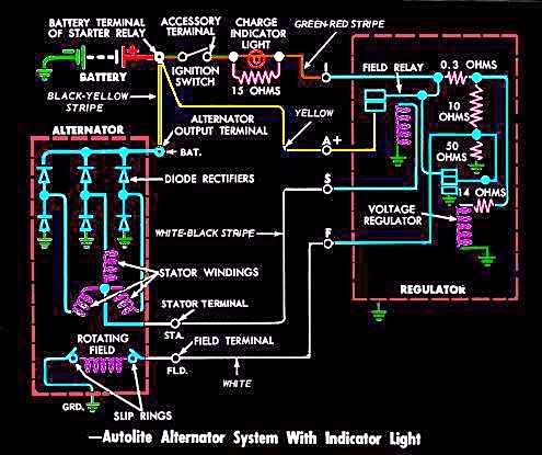
Connect With Us