Close


Page 4 of 4 FirstFirst ... 234
Results 76 to 91 of 91
  1. #76

    Default

    Quote Originally Posted by 48fordnut View Post
    Dean, do you have a second connector. like the one being reeferenced? lmk, jim.
    Hi Jim,

    Not at the moment. I'll have to go to the wrecking yard which isn't a bad thing but I won't be able to go until August. Work, lack of funds, and no time sure puts a crimp on the hobby!

    Dean T
    Proud owner of the one and only Friggin' Futura

  2. #77
    FEP Senior Member
    Join Date
    Dec 2006
    Location
    warner robins ga
    Posts
    544

    Default

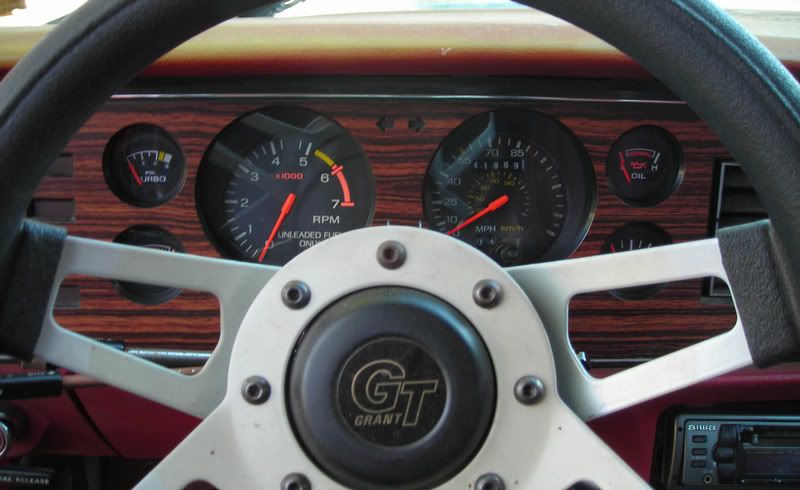
    I think I have one coming. thanks for the reply.I've got the dash installed, but having some problems.
    Will Rogers" common sense is not as common as you think"

  3. #78
    Venomous Moderator Hissing Cobra's Avatar
    Join Date
    May 2002
    Location
    Wareham, Massachusetts
    Posts
    9,721

    Default

    Quote Originally Posted by cleger View Post
    OK guys, here's the scoop:

    I've successfully modified & "calibrated" the 8K 4-cyl tach in my '79 4-cyl cluster for use with my 302.

    Picked up a second cluster (+ the whole dash harness so I got a spare cluster connector) and used the tach in that cluster as a reference. It is a 4-6-8 tach, and all three circuits were present.

    As you may recall, the 4-cyl 8K tach had only a single leg of the three-way switchable engine-selector circuits present on its board. This leg consisted of a single 62K ohm .25W resistor, plus a little 0-100K trimmer pot in series.

    In the page at the link Paul posted in reply #51 above, the author wrote instructions to the effect that one should solder a 100K resistor across the trimmer terminals. I thought about this some, and the more I thought, it didn't seem right. Since the trimmer goes from 0-100K (at the time, I didn't know how high it would go, but figured it was wide-open/0K at one end of its range) running a 100K resistor in parallel with the trimmer would only decrease the upper end of the trimmer's resistance, but it would still drop to zero at the other end of its range.

    Anyhow, turned out I was right, so we can all disregard the advice on that page Paul posted (but is not responsible for!) I tried adding the 100K resistor across the trimmer, but still couldn't get the resistance low enough. Almost, but not quite. The 8K tach would read about 1100 rpm at idle, with the trimmer backed all the way off, while the factory 4-6-8 tach would read 850 or so. Zero ohms is still zero ohms.

    So, what I did instead was go back and remove the 100K resistor I had added, and replace the factory 62K resistor with a 22K I had laying around. This change, in combination with a little adjusment to the trimmer, and the tach was dialed right in. I think a 10K resistor might have been better, but with a 0-100K sweep on the trimmer, there's plenty of adjustability... a 33K, or even NO resistor, probably would have worked as well. if you figure it was set at around 50K at the factory for a total of about 112K with the resistor (for a 4-cyl car) then setting it at 34K to work with the 22K resistor for a total of 66K in an 8-cyl car still leaves the trimmer near enough to its midpoint to allow plenty of adjustability.

    Now, I have to admit, I didn't take all the readings & record everything like I promised. Sorry, I have so many things going on that once I got it working, I put everything back together and buttoned it all up. But here's the thing - if you have a meter, and you want to tackle this, all you need to do is take a reading across BOTH the trimmer (at the factory setting) AND the 62K resistor, record that number, then replace the 62K with a 22K resistor, put your meter back on the traces around the trimmer and your new 22K resistor and use the trimmer to HALVE the old value you recorded. This should leave you pretty much dead-on when you put the tach back in the car.

    The only reason this didn't work for me the first time was that I assumed you'd double the resistance value to accomodate for the 2X igniton pulses from the V8 versus the 4-cyl engine. I even had the 22K resistors but didn't try using them. Turns out, you really want 0.5X. Why tachometer magic works this way is beyond me, but there it is.

    Hopefully this will help the next guy who wants to put an 8K tach in his V8 car. The resistors cost pennies and are in the drawer at your local Radio Shack. At the very least, I can assure all of you that a 22K resistor in place of the 62K will work perfectly. The sweep of the 8K 4-cyl tach and the selectable 4-6-8 tach matched each other exactly, as far as I could tell, from idle up through 3500-4000 rpm.
    Wow! I just came across this thread and was wondering if you could do a step by step writeup on this, complete with pictures and part numbers? I think it would be awesome to add it to the Foureyedpride archive of neat tricks to do.

    I still have the 4 cylinder tach in my Cobra which is currently disconnected (I use an Auto Meter 5" tach) but after reading this, I'd love to get that one working too (I'd also buy the MSD tach adapter to make it work).

    To me, the 4 cylinder tachs are better looking than the 6 or 8 cylinder versions because of the Yellow and Orange coloring that they have. They're certainly more striking!
    Pete Slaney

    1979 Mustang Cobra

    347/T-5/4.30's
    420 rwhp/380 rwt (New Motor)
    11.49 @ 121.86

    306/T-5/4.30's (Old Motor)
    307 rwhp/278 rwt
    12.38 @ 111.38

  4. #79
    FEP Member
    Join Date
    Feb 2009
    Location
    St Augustine FL
    Posts
    209

    Default

    Better late to this thread than never?

    I have a 1981 Zephyr and a 1980 Mustang cluster. I'd like to use the instruments out of the Mustang cluster in my Zephyr but I don't want to lose the column shift indicator.

    Is there a way to transfer the Mustang components into the Zephyr cluster housing so I can keep the column shift indicator? I haven't removed the Zephyr unit, so the answer isn't obvious...

    Tom

  5. #80
    FEP Member C7Z's Avatar
    Join Date
    Mar 2008
    Location
    Belton, Missouri
    Posts
    231

    Default No Indication

    Quote Originally Posted by Tom Wells View Post
    Better late to this thread than never?

    I have a 1981 Zephyr and a 1980 Mustang cluster. I'd like to use the instruments out of the Mustang cluster in my Zephyr but I don't want to lose the column shift indicator.

    Is there a way to transfer the Mustang components into the Zephyr cluster housing so I can keep the column shift indicator? I haven't removed the Zephyr unit, so the answer isn't obvious...

    Tom
    No, they are completely different clusters. You can use the Mustang cluster, but you will lose the shifter indicator.


  6. #81
    FEP Member
    Join Date
    Feb 2009
    Location
    St Augustine FL
    Posts
    209

    Default

    OK - swapped the 1980 dash into the 81 Zephyr. Works fine. Haven't put the new engine in and am still running the 200 six.

    Per the suggestions above, disconnected the temp and pressure switches so as not to fry the gauges, but now the car idles as if cold all the time!

    Is there a way to fix this without blowing the temp gauge?

    Tom

  7. #82
    FEP Member Stormin' Norman's Avatar
    Join Date
    Jan 2008
    Location
    Winnipeg, Manitoba, Canada
    Posts
    401

    Default

    Quote Originally Posted by Tom Wells View Post
    OK - swapped the 1980 dash into the 81 Zephyr. Works fine. Haven't put the new engine in and am still running the 200 six.

    Per the suggestions above, disconnected the temp and pressure switches so as not to fry the gauges, but now the car idles as if cold all the time!

    Is there a way to fix this without blowing the temp gauge?

    Tom
    I just finished installing a 1984 Mustang Dash into my Fairmont Squire. I changed the two senders to the Mustang units, from a 1979-1981 200 I6, (Fairmont, Mustang, Zephyr, Capri). The 1980's have a module that takes engine status and displays it on the Digital Clock in the console. I didn't take it at the Junkyard, because my 1979 didn't have all those sensors. I think they were optional on the Fairmont/Zephyrs. My engine is a 1978 I6.
    1979 Ford Fairmont 4-Eyed Squire (Mexican-Built) 3.3 I6 (200 CID) 4-Speed SROD Trans, Tri-Power

  8. #83
    FEP Member Stormin' Norman's Avatar
    Join Date
    Jan 2008
    Location
    Winnipeg, Manitoba, Canada
    Posts
    401

    Default

    Did a couple other 'customs' too:

    1984 Mustang Dash (2.3L Automatic junkyard target) $40.


    1984 Analog Cougar Clock, cheapy Voltmeter, and Boost/Vacuum gauge. And just cleared the freshair duct in behind.

    Just enough room, after I rewired all the buzzers and relays to the LH under dash area, behind the Fusebox. No more hand scrapes to change a flasher.


    The dark bottom one is the 'Liftgate Ajar' lens, which I took from my Fairmont's cluster (exacto knife). I used my small solder iron and 'welded' the frame plastic back in to replace the original lens in the Mustang panel.


    Wiring was to the original White/Purple warning circuit and then a jumper to the Red/Yellow 12 volt circuit.
    1979 Ford Fairmont 4-Eyed Squire (Mexican-Built) 3.3 I6 (200 CID) 4-Speed SROD Trans, Tri-Power

  9. #84
    FEP Super Member TWR2003's Avatar
    Join Date
    Dec 2007
    Location
    Eastern MA
    Posts
    2,838

    Default

    Florida 5.0 3 gauge over glove box mount


    T
    MF: Shoot pool Fast Eddie.
    EF: Im shootin' pool Fats. When I miss you can shoot.

  10. #85
    FEP Member Stormin' Norman's Avatar
    Join Date
    Jan 2008
    Location
    Winnipeg, Manitoba, Canada
    Posts
    401

    Default

    Quote Originally Posted by TWR2003 View Post
    Florida 5.0 3 gauge over glove box mount


    T
    Very classy setup! Who from?
    1979 Ford Fairmont 4-Eyed Squire (Mexican-Built) 3.3 I6 (200 CID) 4-Speed SROD Trans, Tri-Power

  11. #86
    FEP Super Member TWR2003's Avatar
    Join Date
    Dec 2007
    Location
    Eastern MA
    Posts
    2,838

    Default

    Quote Originally Posted by Stormin' Norman View Post
    Very classy setup! Who from?
    Florida 5.0
    http://www.florida50.com/1979-1986-gauge-holders.htm

    The gauge holder completely replaces the plastic panel above the glove box. Avail in 3 or 5 gauge holders the gauges are angles toward the driver. They are very nice.

    T
    Last edited by TWR2003; 08-07-2009 at 08:53 PM.
    MF: Shoot pool Fast Eddie.
    EF: Im shootin' pool Fats. When I miss you can shoot.

  12. #87
    FEP Member Stormin' Norman's Avatar
    Join Date
    Jan 2008
    Location
    Winnipeg, Manitoba, Canada
    Posts
    401

    Default

    Quote Originally Posted by TWR2003 View Post
    Florida 5.0
    http://www.florida50.com/1979-1986-gauge-holders.htm

    The gauge holder completely replaces the plastic panel above the glove box. Avail in 3 or 5 gauge holders the gauges are angles toward the driver. They are very nice.

    T
    Thanks. We live a sheltered life up here in the North!
    1979 Ford Fairmont 4-Eyed Squire (Mexican-Built) 3.3 I6 (200 CID) 4-Speed SROD Trans, Tri-Power

  13. #88
    FEP Senior Member quarterstang86's Avatar
    Join Date
    Oct 2003
    Location
    A t l a n t a, GA
    Posts
    579

    Default

    Quote Originally Posted by paul78zephyr View Post
    Yes,
    81-86 Mustang unit (uses a single flex circuit)
    If you use a 81-86 Mustang unit it will require more work as you will have to move individual wires in the single F/Z connector to different locations in this connector, move other wires from this connector to the needed second connector, and will need to run new wires to both connectors. The wiring and function pinouts of the 81-86 units two connectors is completely different than the 79-80 units. Also you may need to make some wiring splices in the F/Z harness. Basically it is a somewhat complicated job (but very do-able if you really want to use a 81-86 unit).

    Regardless of whether you use the 79-80 unit or the 81-86 unit you must make some minor wiring changes at the connector on your stock externally mounted alternator voltage regulator. This is because the Mustang units do not have the ALT light and the light is part of the charging circuit.

    If anyone wishes I can get into more detail on the wiring, required wiring changes, and additions.

    Paul
    God I hate to bump this thread but:

    Paul can you please help me. I bought my old car back and according to post #74 in this thread it has a 84 inst cluster in it (reference link below). I drove the car for close to 1k miles but parked it to do some maint work and it wouldn't start after sitting for a week or so, upon keying the ignition it just clickes the starter soleinoid even with a good battery (no engine turnover). I tried a known good battery from another vehicle, same results.

    http://vb.foureyedpride.com/showpost...4&postcount=74

    The car currently has a mechanical oil guage which I plan to remove. 2 of the wires that go back into the main harness near the voltage regulator area were severed or cut and after I traced them go to the factory oil level sensor (it has wire tails on the plug side and they appear to have 12v power while the car is running which spawned my post in the link below). The grey / black wire appears to go from the oil level plug to a factory 90* boot that might go to the factory carb area which is not a major concern for me at the moment because the car has been converted to a holley 2bl setup.

    http://vb.foureyedpride.com/showthread.php?t=80242

    My problem is I'm wondering if NO wiring work was done behind the dash (which I believe none was) or at the external regulator area (which I believe none was) for the factory 1980 charging indicator light as referenced above if that could be creating no start situation I'm in or be a constant drain on the system. As of right now, I have the factory cluster ready and am making plans to swap it back in and patch up the severed wires under hood as I have no interest in making a tach work for the I6 or a mechanical gauge under hood.
    Last edited by quarterstang86; 10-12-2009 at 06:50 PM.
    - Richard

  14. #89
    FEP Senior Member quarterstang86's Avatar
    Join Date
    Oct 2003
    Location
    A t l a n t a, GA
    Posts
    579

    Default

    What would be the most simple mod to releave the charge indicator circuit from the cluster? Being more specific, if I were to install a say 1986 cluster, but only want to have the use of the turn signals, guage lighting and speedo (which is mechanical) could I just do a modification near the voltage regulator and be done?
    Last edited by quarterstang86; 02-23-2010 at 09:38 PM.
    - Richard

  15. #90

    Default

    One solution would be to move the charge indicator and resistor bar over to the stack
    of lights to the left of the gauges. Then find something else to live where the ammeter
    does now. Boost gauge maybe?
    Cheers,
    Jeff Cook

    '85 GT Hatch, 5-speed T-Top, Eibachs, Konis, & ARE 5-Spokes ... '85 GT Vert, CFI/AOD, all factory...
    '79 Fairmont StaWag, 5.0, 62K original miles ... '04 Azure Blue 40th Anny Mach 1, 37K original miles...
    2012 F150 S-Crew 4x4 5.0 "Blue Coyote"... 65 coupe, 289 auto, Pony interior ... '67 coupe 6-cyl 4-speed ...
    '68 Vert, Mexican block 307 4-speed... '71 Datsun 510 ...
    And a 1-of-328 Deep Blue Pearl 2003 Marauder 4.6 DOHC, J-Mod, 4.10s and Lidio tune

  16. #91
    FEP Member Stormin' Norman's Avatar
    Join Date
    Jan 2008
    Location
    Winnipeg, Manitoba, Canada
    Posts
    401

    Default

    When I converted mine from a straight Fairmont cluster to a Mustang/Capri cluster, I learned about one sneaky wire, actually a Fuse Link that runs to the Voltage Regulator back to the Ammeter. (Red or Orange) and I had starting problems until I figured it out. Cost me a regulator too. The regulator is different for the Full Gauge cluster because of it - one or 2 extra wires, but you can add the wires to the connector. And make sure the voltage regulator is grounded.

    I did this to mine - added more grounds and cleaned up the ground contact points on the block and the body bolts - I used solder after cleaning off the rust to keep them clean (old army tech trick on our WWII Deuces)

    Here's the Sticky on improving your grounds:
    http://www.the12volt.com/installbay/....asp?TID=73496

    Heck of a site for car audio and even our Fox-type Cruise Control systems:
    http://www.the12volt.com/
    1979 Ford Fairmont 4-Eyed Squire (Mexican-Built) 3.3 I6 (200 CID) 4-Speed SROD Trans, Tri-Power

Page 4 of 4 FirstFirst ... 234

Tags for this Thread

Posting Permissions

  • You may not post new threads
  • You may not post replies
  • You may not post attachments
  • You may not edit your posts
  •