Close


Results 1 to 14 of 14
  1. #1
    FEP Member
    Join Date
    Dec 2002
    Location
    New Boston, MI
    Posts
    314

    Default Help Identify Some Connectors

    Trying to wrap up the wiring on the 86 3.8-5.0 swap.

    I have enough figured out to make the car run and have working gauges, but have a good bit of wiring with nowhere to go.

    If anyone has any ideas where these plugs go, let me know. In the meantime I will be digging through diagrams.

    Thanks


    Sent from my iPhone using Tapatalk

  2. #2

    Default

    Wish I could help, my wiring is completely different than yours.
    79 Zephyr, 4.6L 4v/4r70w swap, with team z front and rear suspension, 8.8 and upgraded brakes and coil overs. Running Holley Terminator X Max.

  3. #3
    FEP Member
    Join Date
    Dec 2002
    Location
    New Boston, MI
    Posts
    314

    Default

    Quote Originally Posted by massacre View Post
    Wish I could help, my wiring is completely different than yours.
    Just ordered a EVTM for the Cougar on EBay. That should help fill in the blanks.


    Sent from my iPhone using Tapatalk

  4. #4
    FEP Super Member xctasy's Avatar
    Join Date
    Jun 2012
    Location
    Dunedin 9011, New Zealand, South Pacific
    Posts
    3,961

    Default

    Quote Originally Posted by Walking-Tall View Post
    Every time I see a post like this one at this forum (this one, a second time), coupled with the usual and loud sound of crickets, I have to ask... where are all the electronic fuel injection cheerleaders now?... .

    Sorry for the candy coated chocolate pebble words....I put them somewhere!


    The CFi 3.8 computer to 5.0 non HO SEFi swap has a whole punch of incongruent or left over bits due to the EECIV's different pinout wires being feed to other geographical parts of the 5.0 Port EFi. .


    1. the single o2 sensor verses twin O2 sensor, although the ECM has an internal earth for it, its got a very different hook-up.

    2. the 2-bbl 1.4375" throttle body ISC Stepper motor verses the the SEFI version of 1 big 55 mm throttle body idle control

    3. the Dual Synch TFi having an additional second type of fuel signaling as well as ignition signaling

    4. The EGR having a different control system


    Just be glad your not doing 5 and 6.

    --->5. Any conversion to Mass Airflow further puts another change.

    --->6. If its now a 5 speed 5.0 SEFi rather than 3.8 C5, then you have the O2 sensor wiring to deal with.

    http://vb.foureyedpride.com/showthre...d-thread/page5


    Quote Originally Posted by Walking-Tall View Post
    Black spaghetti, "brain", CFI throttle body, and TFI distributor out, REEEJECTED! (crankshaft @ #1 compression TDC)...


    I swear the front of the car raised about 1/2" after removing all this $hit...

    Battery?

    http://vb.foureyedpride.com/showthre...nversion/page2

    1980 Cobra with 1986 SEFi


    with a Ram Air cone filter and stock battery position, you don't need to do the 180 degree manifold swap....

    Quote Originally Posted by xctasy View Post
    .......


    .

  5. #5

    Default

    Quote Originally Posted by 86lx View Post
    Just ordered a EVTM for the Cougar on EBay. That should help fill in the blanks.


    Sent from my iPhone using Tapatalk
    I recognize some of the connectors as being the same,, but the wires seem to be different colors than yours.
    79 Zephyr, 4.6L 4v/4r70w swap, with team z front and rear suspension, 8.8 and upgraded brakes and coil overs. Running Holley Terminator X Max.

  6. #6
    FEP Super Member xctasy's Avatar
    Join Date
    Jun 2012
    Location
    Dunedin 9011, New Zealand, South Pacific
    Posts
    3,961

    Default

    Now Brad and Joe will certainly need some sanity time, but the details they have shared have been excellent.


    MAF car rewiring is an Item 5 and 6 thing, but the 5
    33.59 minutes here is very beneficial to see what there is stock on a later T bird 5.0

    "Rewiring a Ford EEC IV "speed density" harness to a "mass air" harness" by

    "BadShoeProductions
    6.91K subscribers"


    https://youtu.be/mnnTgXkHU9Q


    Quote Originally Posted by NAVYCAT View Post
    I just finished 4 days of splicing and wrapping wires....... what a PITA! just need to check wires with a meter and then install into the dash, but need to pain it first. also ordered 4 new rubber items so she can sit on the ground again


    02 sensor. The pin colors and wiring will be different between the 3.8 CFi Mustang and 5.0 Std Output, but the EVTM (Electrical Vacuum Troubleshooting Manual) will help you some.


  7. #7

    Default

    Quote Originally Posted by massacre View Post
    but the wires seem to be different colors than yours.


    That potato sack as a dress, does not make you look fat.
    That dress that looks like a table-cloth reject, does not look ugly.
    Ford really does care about the exact wire colors that are installed in the cars.


    I have 3 different Ford factory documents for the wiring that was in my '86 T-bird. Not one matched the main wiring harness from the main power feed (that got eaten through by battery acid). Also, all three wiring diagrams had minors differences for the main wiring harness.
    I was trying to figure out if I could leave some wires alone. As it ended up, I had to remove the MC and brake booster in order to get enough play and visibility into the colors, in order to replace all of those wires. I wasn't going to take a chance of getting stranded, or loosing something important, by one of those wires breaking internally after being compromised by battery acid fumes.

    A good part of it comes down to luck. Most of the cars will match some wiring diagram.
    But, some, like my '86 t-bird, may have wiring that is different for what ever reason (start/end of model year, shortages, etc).


    Btw, yes, those sweat-pants you have on, are completely acceptable for a job interview. ;-)

    Good Luck.

  8. #8
    FEP Super Member xctasy's Avatar
    Join Date
    Jun 2012
    Location
    Dunedin 9011, New Zealand, South Pacific
    Posts
    3,961

    Default

    86lx


    While I was cross checking the 8 wire F150/Lincoln and later 95 Mustang 5.0 DTC link, I saw again 4eyedblind's really nice summary of the later 86-95 EECIV wiring protocol. Brad and Joe have been working through this too.

    This is a MAF car, but as long as you can see the MAF and Non MAF Speed Density differences from BadShoeProductions, you got mail.


    Quote Originally Posted by 4eyedblind View Post
    Just use the 95 engine harness and ECM, then you don't have to convert anything.

    All you'll need to do is merge a few wires into the existing subsystems in the car (about 6) and she'll run.

    If the 95 stuff is similar to the 88 I just swapped into my 86 CFI V6 car, there are only two wires in the grey connector that are mission-critical Both red with different colour stripes.

    One is crank and run power and one is crank only.

    Then 4 wires in the supplementary green 8 pin connector next to the EEC.

    Those are ignition source, FPR/Inertia/FP.

    There is also a single hot wire from the starter solenoid going in here on the 86.

    There is main battery EEC power, then there are three mission critical grounds:

    the EEC dedicated ground (fuse holder looking thingy near batt,


    engine block ground near firewall

    and a small ground near the EEC box itself.

    That's it...it's pretty dumb actually.

    You may have to do even less than I, as you already have a V8 car.

    You may just be able to plug in the two round 8 pin connectors from the 95 harness to your 86 stuff.

    Check the pinouts though.

  9. #9
    FEP Super Member xctasy's Avatar
    Join Date
    Jun 2012
    Location
    Dunedin 9011, New Zealand, South Pacific
    Posts
    3,961

    Default

    http://vb.foureyedpride.com/showthre...eed-parts-info

    Start with the most difficult first, then go back through the list.

    Everything is itemized as far as possible.

    Hardest item is : Your existing EGR. The crossover ports are at the back of the heads, and commonly are blocked up, and don't be surprised if a head needs removal to service it.

    Normally, that's a good time to add alloy heads painted natural iron color, or GT40P's with 90 degree angle plug spark leads. The GT40p's have smaller exhaust valves, and work fine with the Verlie stock E5 266 degree at lash cam.


    In terms of getting the parts put back on, another note:-

    Everything from a 1986 emission system was technically designed for 50 000 mile "without intervention" Federal emissions durality, and the hard items were supposed to last the lifetime of the car "with intervention".

    Ford expected some of the cars to be used in Rust Belt areas, but really, normal life for a uni body car in the Calcium Magnesium Acetate or Rock Salt covered winter roads would be 10 years. Based on worldwide studies, normal life with Yearly inspection intervention work is 17.5 years for a Ford in a non salted road environ. The statistics for vehicle life has always been public domain from places like Sweden and the West German TUV from the 50's to date. Fords Canadian and US data isn't kept to the same standard, but form what I've seen the figures are accurate. The Europeans and most North Americans have yearly car replacements, so vehicle's that haven't had write off accidents that can be kept in service sometimes are scrapped, so the average life span for various Ford models is coming down.

    The "moving average vehicle life with intervention" is public domain, but has some of those issues. A little bit like warranty claims per 1000 vehicles and Red Book Values for 3 year old cars.

    Fox Fords, despite the "Rust Tang" label added by many, are true survivor cars.

    see http://vb.foureyedpride.com/showthre...on-amp-Testing

    Quote Originally Posted by xctasy
    Name it and claim it time.

    Haystack found what I did, no common 1986 GT Emission/ Vacuum Lines diagram.

    Quote Originally Posted by Haystack View Post


    Should go to the tab/tad stuff. My guess is that if the vacuum lines are missing, so is the rest.


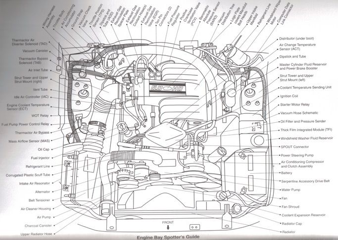
    1, 2, 14, 18, 20. 41, 43, 49, 50, 51, 52 and 53 are the critical EGR related parts.

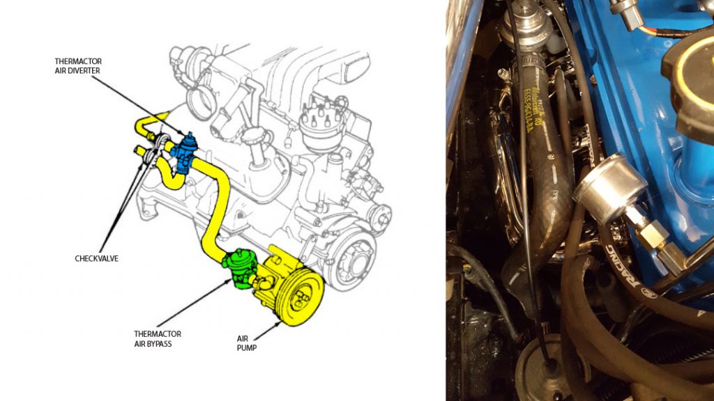
    1. Thermactor Air Diverter Solenoid (TAD) - Directs thermactor air from the rear of the cylinder heads to the exhaust H pipe after warm up
    2. Thermactor Air Bypass Solenoid (TAB) - Vents thermactor air during periods when it is not needed (primarily cold starts)
    3. Vacuum Storage Canister - Stores Vacuum to prevent interruption of services during wide open throttle
    4. Throttle Body - Regulates the amount of air entering the engine
    5. Air Inlet Hose - Directs air into the throttle body from the mass air meter (Mass air car) or the air box (Speed Density Car)
    6. Idle Air Bypass Valve - Regulates the amount of air needed to maintain a smooth idle
    7. Engine Coolant Temperature Sensor (ECT) - Reports the coolant temp to the computer
    8. Injectors - delivers fuel sequentially to each cylinder
    9. Oil Filler Cap
    10. WOT Cutout Relay - Kills AC compressor during wide open throttle
    11. Fuel Pump relay - The computer activates the fuel pump through this relay
    12. Mass Air Flow Sensor - The Electronic device used to measure the amount of air passing through the meter
    13. Mass Air Flow Meter - Electrically measures the amount of air entering the engine and reports the information back to the computer
    14. Thermactor Bypass Valve - Directs the flow of air supplied by the thermactor (fresh air) pump
    15. Alternator
    16. Belt Tensioner
    17. Air Silencer - Used to muffle incoming air noise (located in the fender)
    18. Canister Purge Solenoid - Allows fuel vapors from the carbon canister to enter the intake manifold
    19. Air Cleaner Housing - Contains the air filter
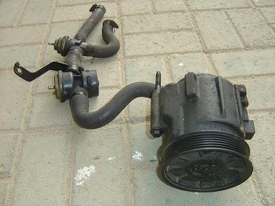
    20. Thermactor Air Pump - Delivers high volume, low pressure fresh air to the exhaust system
    21. Water Pump, Fan, and Fan Clutch
    22. Air Conditioner Condenser Connections - Attaches refrigerant lines to air conditioning condenser
    23. Center Line Crash Sensor - 90-93 only - triggers air bag in the event of a front end collision
    24. Radiator
    25. Radiator Cap
    26. Coolant Reservoir and Low Coolant Switch (if so equipped)
    27. Power Steering Pump
    28. Battery
    29. Air Conditioning Compressor
    30. Spout Check Connector - Must be unplugged when checking initial ignition timing
    31. Windshield Washer Reservoir
    32. Vacuum Hose Diagram
    33. Ignition Coil - under plastic cover
    34. Starter Relay - under plastic cover
    35. Coolant Temperature Sender - Relates coolant temperature to the gauge in the instrument panel
    36. Engine Oil Dipstick
    37. Electronic Distributor - Controlled by the computer
    38. Front Strut Insulator and Camber Adjustment Plate
    39. Upper Intake Plenum
    40. Brake Master Cylinder and Booster
    41. VIP Test Connectors - computer test ports
    42. Windshield Wiper Motor
    43. Vacuum Distribution Tee - From left to right the connections are: vacuum source (intake manifold), unused, vacuum reservoir, speed control servo (if equipped with cruise), power brake booster
    44. Air Charge Temperature Sensor - Reports the temperature of the air in the intake manifold to the computer
    45. Barometric Absolute Pressure Sensor (BAP) - Reports barometric air pressure to the computer
    46. Positive Crankcase Ventilation Valve (PCV Valve) - relieves crankcase pressure
    47. Fuel Pressure Regulator - Uses intake manifold vacuum to lower the fuel rail pressure during low rpm operation
    48. 10-pin connector - Mates the engine wiring harness with the main wiring harness and the EEC computer
    49. EGR Vacuum Regulator Solenoid - Controls the vacuum which opens the EGR valve
    50. EGR Valve and EGR Position Sensor - Allows exhaust gases to enter the intake passage during various engine speeds. Reports valve position to computer
    51. EGR Spacer - Provides a hot gas passage to and from the EGR valve
    52. EGR Coolant Hoses - Circulates coolant through the EGR spacer
    53. Throttle Position Sensor - Relates the percentage of throttle opening to the computer
    54. Transmission Dipstick Tube - Auto trans only
    55. Crankcase Ventilation Tube - Allows crankcase fumes to enter the intake system
    56. Wiring Harness - Cable system that connects all of the engine's electrical components to the computer in the passenger side kick panel
    57. AC Accumulator - Provides a storage area for the refrigerant in the AC system and houses a chemical drier that removes moisture from the refrigerant
    58. Vacuum Check Valve - Allows air to flow in only one direction in order to keep vacuum storage canister fully charged
    59. Hood Ground Strap
    60. AC Low Pressure Switch - Will not allow the air conditioner compressor clutch to energize if refrigerant pressure drops to an unsafe limit

    The EGR Vacuum Control solenoid & EGR Vent valve solenoid works on a warm engine. You pull the vacuum line off the EGR and hold your finger over the line while you rev the engine. You should feel vacuum on the EGR line when you rev it, and then it should go away at idle. The EGR Vacuum Control solenoid lets the vacuum through, and the EGR Vent valve solenoid releasing the vacuum.

    The computer activates the EGR Vacuum Control solenoid, and then it looks at the EGR sensor via its voltage to see how much it opened.

    It does this under Pulse Width Modulation, back and forth, modulating the the amount of inert EGR gas to the engine.


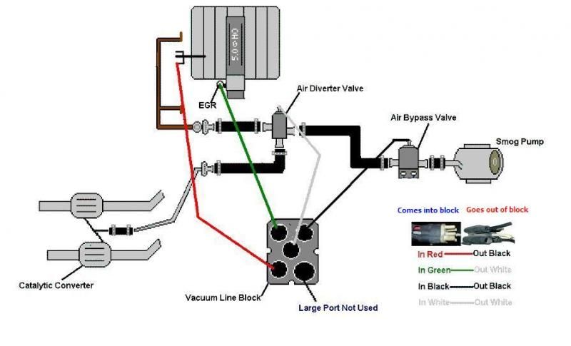
    The four element Secondary AIR system is separate, but nothing works in isolation.


    * raided from http://foxstang.com/fox-mustang-smog-system-help/


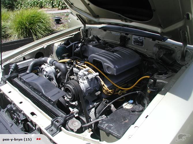
    The 86 upper intake has unique porting


    The 86 PCV long hose that does a 180 degree loop

  10. #10
    FEP Member
    Join Date
    Dec 2002
    Location
    New Boston, MI
    Posts
    314

    Default

    Quote Originally Posted by xctasy View Post
    86lx


    While I was cross checking the 8 wire F150/Lincoln and later 95 Mustang 5.0 DTC link, I saw again 4eyedblind's really nice summary of the later 86-95 EECIV wiring protocol. Brad and Joe have been working through this too.

    This is a MAF car, but as long as you can see the MAF and Non MAF Speed Density differences from BadShoeProductions, you got mail.
    Very helpful. Thank you.


    Sent from my iPhone using Tapatalk

  11. #11

    Default

    Quote Originally Posted by stangPlus2Birds View Post


    That potato sack as a dress, does not make you look fat.
    That dress that looks like a table-cloth reject, does not look ugly.
    Ford really does care about the exact wire colors that are installed in the cars.


    I have 3 different Ford factory documents for the wiring that was in my '86 T-bird. Not one matched the main wiring harness from the main power feed (that got eaten through by battery acid). Also, all three wiring diagrams had minors differences for the main wiring harness.
    I was trying to figure out if I could leave some wires alone. As it ended up, I had to remove the MC and brake booster in order to get enough play and visibility into the colors, in order to replace all of those wires. I wasn't going to take a chance of getting stranded, or loosing something important, by one of those wires breaking internally after being compromised by battery acid fumes.

    A good part of it comes down to luck. Most of the cars will match some wiring diagram.
    But, some, like my '86 t-bird, may have wiring that is different for what ever reason (start/end of model year, shortages, etc).


    Btw, yes, those sweat-pants you have on, are completely acceptable for a job interview. ;-)

    Good Luck.
    So I’m not sure if you are agreeing with me or not lol. But I appreciate your response.
    I’m sorry you had such bad luck with your wiring.
    79 Zephyr, 4.6L 4v/4r70w swap, with team z front and rear suspension, 8.8 and upgraded brakes and coil overs. Running Holley Terminator X Max.

  12. #12

    Default

    Quote Originally Posted by massacre View Post
    So I’m not sure if you are agreeing with me or not lol. But I appreciate your response.
    I’m sorry you had such bad luck with your wiring.
    I'm agreeing with you.
    And, warning others.
    I've mentioned the above, a few times before.

    From what I've read on the forums over the many years, at times, the Factory could be loosey goosey with what they installed in vehicles, as long as the vehicle functioned as designed. This is especially true near model-year switch-overs.

    Iirc, sway-bar bushing size was another thing that could be swapped - if they needed to get vehicles out-the-door to the dealers, and there was a shortage.
    Btw, the nice huge ?11x17? wiring schematics that come in a binder are nice to have. They're available on ebay, every now and then.

    Good Luck!

  13. #13
    FEP Super Member xctasy's Avatar
    Join Date
    Jun 2012
    Location
    Dunedin 9011, New Zealand, South Pacific
    Posts
    3,961

    Default

    The TAB/TAD 86lx.


    Quote Originally Posted by Magnetic82 View Post
    Update:

    I may have been looking in the wrong place. I need to examine the passenger side cylinder head smog passage. Might explain things better. Got my signals crossed.

    But also discovered another detail. Here's the 86 factory wiring diagram of the TAB and TAD solenoids.

    Looks like the TAD has two wires and TAB has three. TAD shows a light green with black wire. TAB has white with red wire.
    Here's what is on my car, 1986 GT. Factory.

    If the TAD with two wires needs light green with black, then the set up is reversed on my car. Right?
    Might explain the code 44 and the engine running hot in days passed.

    I have a Monitor to plug in and check but not today. Need more time to do that. I suppose I can just 'reverse' the vacuum hoses and been done with it. I think that was the solution with overheating a few years ago. But still the code 44 so might still need to probe the passages and make sure they are clear.
    Other books show three wires a piece but not the factory literature. 2 for TAD. Nice way to remember it, eh?

    Ideas most welcome. I'll keep at it.
    Thanks all.

  14. #14
    FEP Member
    Join Date
    Dec 2002
    Location
    New Boston, MI
    Posts
    314

    Default

    Quote Originally Posted by xctasy View Post
    The TAB/TAD 86lx.
    Thanks for this. We removed the smog pump and the TAB/TAD solenoids. Those connectors are tucked away behind the passenger strut tower.

    I think all we have left is to identify some wiring for the alternator and AC.

    Ordered a EVTM for the donor Cougar. That should be helpful.

    After that I can go through and clean up the rats nest.

    Then it’s on to wiring up a fan controller and oil pressure/water temp gauges.

    The fun never ends.


    Sent from my iPhone using Tapatalk

Posting Permissions

  • You may not post new threads
  • You may not post replies
  • You may not post attachments
  • You may not edit your posts
  •