Dang, I broke the CE-130 power valve. Snugged it down just a little too tight. Got the car all put back together with another power valve. After buttoning it up and leak checking it, I went and got the mail. There was a new CE-130 power valve in the mail box! How's that for timing? So I drained the bowl, again, and put in the new power valve.
I tested the old CE-130 (before breaking it) and the first stage opened at 11"Hg and the second stage at 5"Hg. The new CE-130 opens at 12"Hg and 6"Hg.
Compared to the CE-126 which opens at 10"Hg and 4"Hg. To know when each stage opens I stick the fuel side of the valve in my lips and blow while sucking on the vacuum side with a hand-held vacuum pump. The CE-126 is noticeably more restrictive than the CE-130 during the first stage so it's gotta have a smaller 1st-stage orifice.
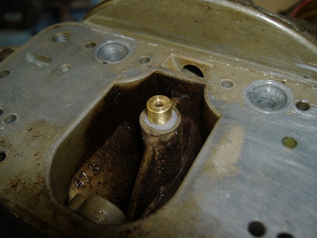
Speaking of orifice... Since I broke a CE-130 in half I just kept breaking it until I got to the orifice in order to measure it. I was surprised to see only a single 0.021" hole. I always pictured it as two holes, I guess cause I'm used to seeing two PVCRs. Do the math on that, since you have one tiny hole feeding both jets, the first stage is equivalent to raising my 61 jets up to 63 jets. That's a pretty small jump considering the second stage is closer to 73 jets.
So how did it work. For the first time ever it's not stumbling at 9"Hg! No, now it's falling down somewhere between 10-11"Hg.

I'll pick up a 9.5, maybe 10.5, power valve and give it a shot.


 Reply With Quote


Connect With Us