Gad this is so easy for me,
Sask84gt.
Everyone hates this Vehicle Emission Control Information detail sh!zEn but me.
Tree tree, one two three, please grow very big for me.
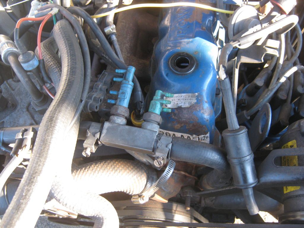
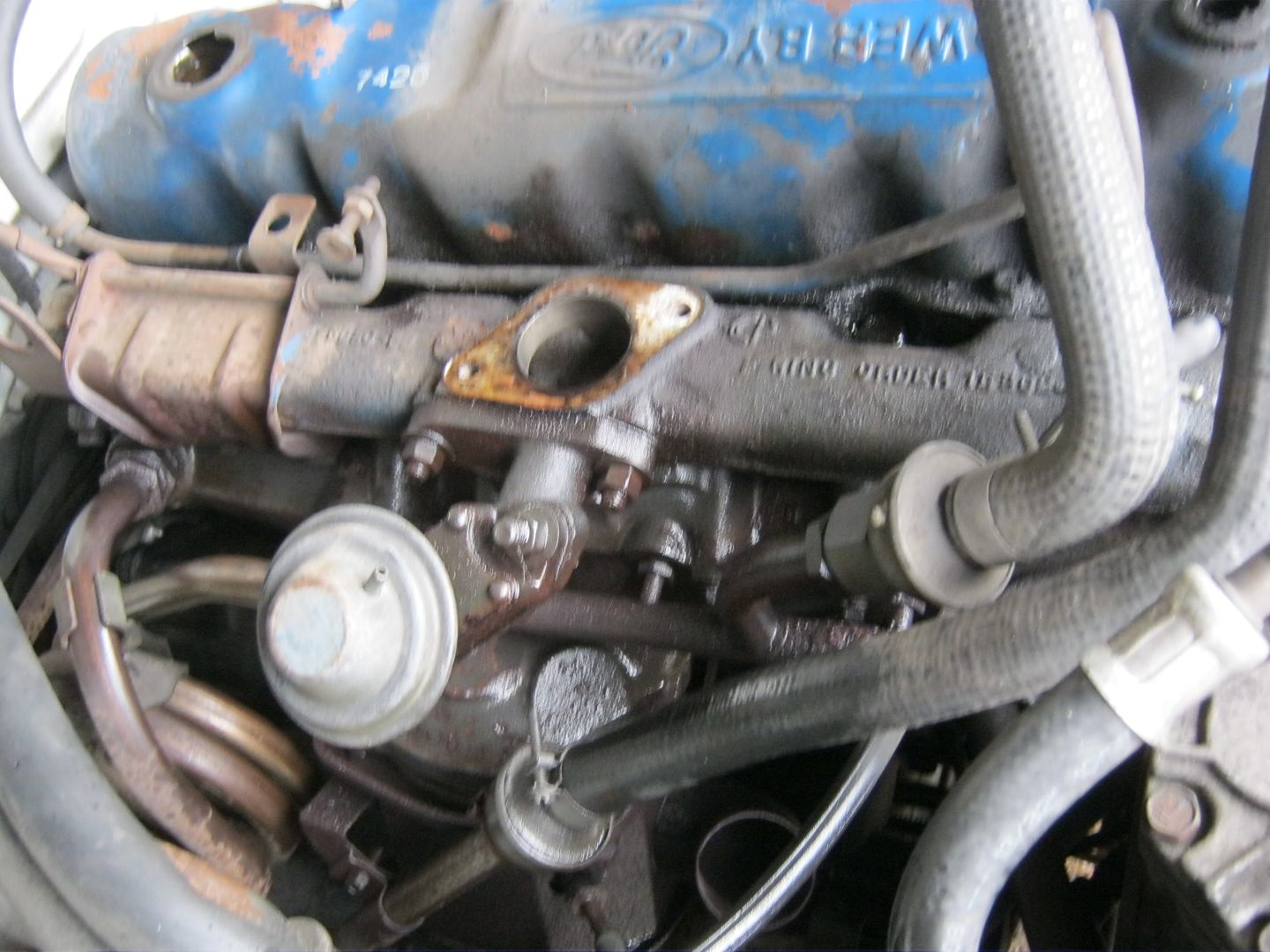
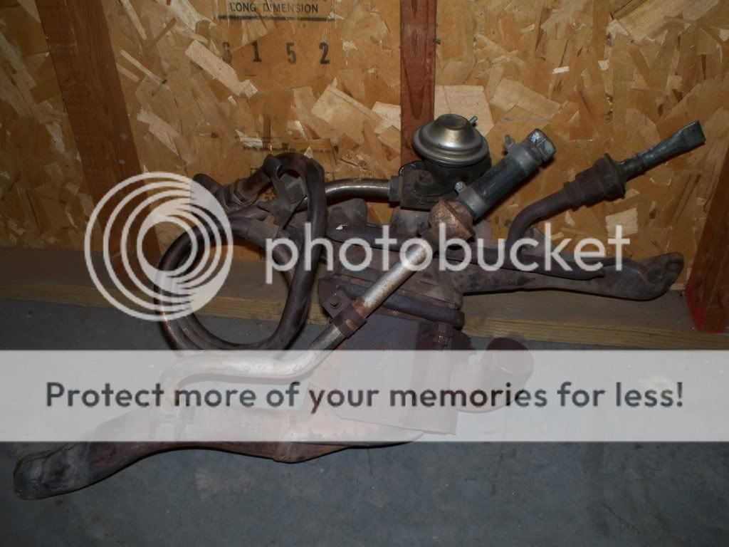
Just use the 1980-1983 B or X code 3.3 six water line, and fit the red and green line to that. The hose just has to have an always on hot water source, and you can then affix your Red and Green stock parts to it.
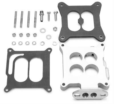
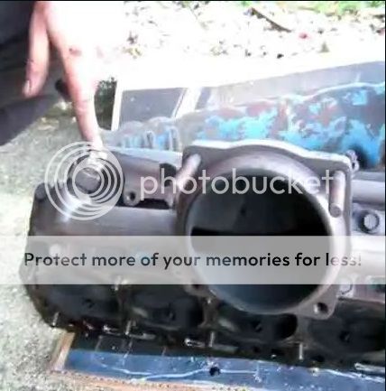
Here is an 81 with the adaptor I have spoken of many times before.
It has the Blue and Green TVS. This may be troubling to some of you, but it is just a simple matter to use it.
You just bolt in the Red and Green tree

Fellas, Ford spent bizzillions making the basic emission stuff work on engines that had no water cross over.
Any engine can benefit from stock hook-ups.
The 1983-1985 4bbl 5.0's had well over 100 emission control devices alluded to on the VECI diagram.
The best forms of the art are the colored M code 4BBL 5.0 HO Mustangs of 1983-1985.

As for me, I've spent weekends driving emissions festooned 216 hp 4bbl Carter Thermoquad 351C's (Baker Constructions silver Fairlane in 1989 while doing mine survey work, and a streatched 200 hp 4.9 liter 1982 LTD Limo )
Seven years with an emission control and propane in-line cross flow six
And 4 years of 91 hp 1946C Holley 1-bbl cold starts with the engine idling for days on end. (2011-2015)
And emission control was definitley the
best thing about the 1981 six cylinder Mustang, the 1976 Fairlane 5.8, and the 82 5.8 LTD.
Take one thing away, and the whole system falls like a twin deck of cards.
The following is the best list I could manage.
0 VECI: Vehicle Emission Control Information, a Diagram detail
1 A/CL: according to Ford, that IS the air cleaner
2 A/CL DV: Air Cleaner Duct & Valve
3 A/CL BI MET: Air Cleaner Bi-Metallic Valve
4 A/CL CWM: Air Cleaner Cold Weather Modulator
5 ACV: Air Control Valve
6 AIR: This is a Secondary air injection Ford calls the Thermactor, short for Thermal Reactor. CA vehicles are installed with it as standard. Air Injection Reaction is what it stands for.
The thermactor system consists mainly of the air pump, the air pump diverter and bypass valves, TAB and TAD solenoids (if equipped) and the catalytic converter.
7 AIR BPV: Air Bypass Valve (aka Thermactor Air Bypass TAB)
8 BV: Bowl Vent (on top of the float tanks)
9 CARB: Carburetor
10 CPRV: Canister Purge Valve ( PURGE CV : )
11 DIST : Distributor of course.
12 EGR: Exhaust Gas Recirculator
13 EFCA: Electronic Fuel Control Assembly (ie Central Fuel Injection or Throttle Body Injection on EECIII and EECIV CFi "EFI" Fords)
14 FLTR: Filter
15 FPR: Fuel Pressure Regulator
16 IVV: Thermactor Idle Vacuum Valve
17 MAN VAC: Indicating Manifold vacuum-Vacuum source
18 MAP: Manifold Absolute Pressure (BMAP: Bariometric Manifold Absolute Pressure, in the case of CFi 5.0 EECIII cars from 1979 to 1985)
19 SOL V: Solenoid Valve
20 SV-CBV: Carburetor Fuel Bowl Solenoid Vent Valve
21 V VAC: short for Vacuum
22 VCKV: Vacuum Check Valve
23 VRESER: Vacuum Reservoir (Actually VRESER just stands for Vacuum Reservoir. It may or may not have a valve or Solenoid Valve inside it.
24 VREST is a vacuum restriction, usually at the thermally controlled valve on top of the thermostat housing.
*On 87 4V 460 F250 truck it is a simple Blue plastic orifice inline with the vacuum line. On 81 IV 200, Pink plastic orifice inline with the vacuum line
25 VRV: Vacuum Regulator Valve
26 VRDV: Vacuum Retard Delay Valve, as these can be used on more than just the distributor.
27 TVS: Thermal Vacuum Switch, and is different to a Dashpot. On Fords these are usualy located in the air cleaner. IMPORTANT: Color defines Fords VECI Name, although clearly stamped TVS, they are called Item 4 A/CL CWM: Air Cleaner Cold Weather Modulator's and may be Green, Purple, Grey, White, Black or Yellow with a different rating based on color.
28 TVV: Thermal Vent Valve. On Fords they are mostly controlled by ambient air temps. Simular to a TVS. Located between the carb and the charcoal cannister.
29 PVS: Ported Vacuum Switch: Very similar to TVVs except on Fords they are used in the cooling system and are controlled by water temps.
30 PURGE CV: Vapor Canister Purge Valve
31 EVAP CANISTER ASY
32 ISC: Ford refers to theirs as an Idle Speed Control (ISC) solenoid. Others mis-use the Idle Air Contro (IAC) term
33 Idle Boost Solenoid (Orange Knob on 81, 82, 83 A/C Equiped 3.3's) or Throttle Kicker Control (TK)
34 Carburettor Throttle Solenoid Positioner (Anti Dieseling Valve/Idle Stop Solenoid)
35 S Spark Port
36 EGR Actuator
37 E EGR Port
38 CATALYST or CAT is catalytic converter (VECI Diagram detail is CATALYST)
39 ENG is engine;
40 ACT - not sure, but on EFIs it means Air Charge Temperature sensor
41 Inlet Air Temperature Control
42 Green DVCV 2 port PVS Vaccum Switches
43 Blue TCVV 3 Port Vaccum Switches
44 Dual Diaphram Distibutor
45 Black SDV Cold Start Spark Delay valve
46 Black SDV EGR Vaccuum delay valve
47 Deceleration Valve (PVS Cold Start lockout Dampened, Non Dashpot)
48 Non dampened or 2 port PVS (dampened) control EGR
49 Attitude and Position Fuel Trap
50 PVS Vacuum with Sintered Line Filters
51 Close Limit primary or Main Jets,
52 Lead plug sealed idle screws
53 Carburettor Throttle Solenoid Positioner (Repeat of 34, Anti Dieseling Valve/Idle Stop Solenoid)
54 Evaporative Emmission Control System
55 Anti Backfire Valve
56 EGR Valve Actuator
57 Vacuum Regulator/Solenoid
58 SOL V: Solenoid Valve ( Repeat of 19 )
59 Venturi Vacuum Amplifier
60 Load Control Valve
61 EGR B/P Transducer
62 Signal Conditioner
63 Ported Pressure Switch
64 Vent Valve Vacuum
65 Vacuum Controlled Switch
66 Vacuum Controlled Switch (Cold Temp)
67 Vacuum Controlled Switch (Decel Idle)
68 Vacuum Delay Valve
69 Vacuum Vent Valve
70 Delay Valve Two Way
71 Ignition Timing Vacuum Switch
72 Ignition Pressure Switch
73 TK (Throttle Kicker)
74 Mushroom caps for charcoal fuel vapor canister vents (VECI Diagram detail).
75 CARB BV (VECI Diagram detail, Repeat of 8 BV: Bowl Vent [on top of the float tanks])
76 FUEL T (VECI Diagram detail)
77 SLEEVE (VECI Diagram detail)
78 TO ATMOS (VECI Diagram detail)
79 VAC-SWITCH ASSY (VECI Diagram detail)
80 SA-FV: Separator Assembly Fuel / Vaccum (VECI Diagram detail)
81 PCV: Positive Crankcase Ventilation (VECI Diagram detail)
82 A : Area to apply Hand Vacuum Pump test (VECI Diagram detail, often multiple 2X)
83 Anti B/F : Anti Back Fire
84 HEAT VLV : Heat Riser Valve (Drivers side Header Heat Riser in some cases)
85 HICV : Hot Idle Control Valve
86 VOLTM : Vacuum Operated Load Throttle Modulator
87 VOTM : Vacuum Operated Throttle Modulator (Variation on 34 and 53 Carburettor Throttle Solenoid Positioner, 73 TK [Throttle Kicker])
88 VR/S: Vaccum Regulator Solenoid
89 VRDM : Vacuum Retard Delay Modulator
90 DUMP : Dump (Open to Air, VECI Diagram detail)
91 DIV : Diverter (VECI Diagram detail)
92 LCV : Load Control Valve
93 Vac Switch Assembley (Like SOL V, only vac operated, Refer Item 33, Idle Boost Solenoid [Orange Knob on 81, 82, 83 A/C Equiped 3.3's] used as a kind of Throttle Kicker Control [TK], but to contol base idle)
Now, go see
http://vb.foureyedpride.com/showthre...ture-included)
Mike and Jeff are the best assets on this forum for emission devices!


 Reply With Quote


.jpg)

Connect With Us