
fltr


fltr
Last edited by gr79; 03-18-2019 at 05:14 PM.

Yes!! GR and X thank you so much for taking the extra time and effort to answer, scan and post such valuable information and previous great links on this recurring subject Too bad Ford did not document the diagrams better for us as they did '82 up! I have spent many, many hours (multiple times over the years) going over these diagrams and thread links and finally, slowly it is starting to sink in and help. I believe I have most of what I need to start doing all of my spaghetti tracing now!
Current FEP:
1980 M81 McLaren Carb Turbo 2.3T #003P ... IT'S ALIVE after a 22 year slumber thread!
Past FEP:
1986 Capri GS 5.0- very missed but in goods hands
1985 LTD SSP- quick little fox 5.0

Okay, I may be off base here, but recheck the obvious.
First, assume 49 states, and check the basics.
See
Diagram 40 of 107 http://myzephyrs.com/VAC_2.3/0-01H-R10%201980.html
Diagram 41 of 107 http://myzephyrs.com/VAC_2.3/0-01H-R15%201980.html
(Both the same diagram).
SOL V closest to driver side operates the carb primary throttle barrels "VOTM".
The brown tinged color VOTM at the back of the carb is a non TSP type without a solenoid.
No matter what the type, you use a Mitivac or hand held vac pump to test the 20" Hg and 10" Hg pressure bleed down specs.
The passenger side SOL V controls the items which after 1982 were called TAB/TAD two stage upstream and downstream AIR.
Once all those checks and balances are working, it won't " conk out" if the two stage SOL V's are "activated" or de-engergised.
Normally, an old VOTM in regular service will work fine. Its designed to exceed 50000 miles if regularly used. If its been out of action, it may be leaking and not operating as Ford intended.
The four lines from the two SOL V's need to be traced and tracked.
Now some extra secondary thoughts.
Your A/C unit is factory, and I'm thinking its got five total additional A/C only parts from
Diagram 42 of 107. http://myzephyrs.com/VAC_2.3/0-01S-R11%201980.html
For all descriptive purposes, your car may in fact have a totally CA emissions line addition, as it clearly has the five element catwalk null knobs.
Potentially, Ford can re-purpose those depending final market.
.
In your case, there is no non return valve diode, or "check valve" on yours at the green knob , a VDV.
One of these which gr79 has described.
Some VDV are unlisted on the VECI's for turbo 2.3's.
In your case, it looks to be described different to gr79's.
Count your Five (5) knobs, and just check if the routing has been arranged as per the CA VECI 42 of 107.
Ford probably re-purposed them for CA A/C cars.
I'm looking for:-
the extra VCV , FLTR and ACV lines ,
extra MAN PLNM (plenumb) take-off junction,
re-routed A/CL CWM take-off.
an additional two control solenoid for CA spec engines, (they are eventually a five fingered vac junction off 1 RNR),
The 4RNR is additionally shown as being teed slightly differently, although I'm not certain how this occurs.
The 1 RNR and its five junction knobs on the catwalk or what you might call the fender mounted Solenoid "null" knobs operate as an idle throttle kicker for the A/C via ignition advance. The orange one is the same as my TSB VOTM control common to 1981 3.3 liter Mustangs.
Check those items again.
The A/C CA version has five (5) technical inputs.
The 49 states, only three can be adjusted under the VECI instructions.
1. green TURBO light, ignition timing retard under boost.
2. turbo boost related item under hood is the two level sensor assy on fender.
3. For Pink or Red maybee, over boost warning light/buzzer.
The 3 or 5 point 1 RNR related items are the same on the car, but will have been re-purposed for A/C equipped cars I'm guessing.
Last edited by xctasy; 01-24-2019 at 01:02 PM.
About Respect https://www.youtube.com/watch?v=2bk9WG8KWW0
X's Album http://vb.foureyedpride.com/album.php?albumid=2922
Oz JPS Stang http://www.nzmustang.com/Images/Hist...cecars/jps.htm
4V (A)US Race V8's https://www.youtube.com/watch?v=Tqk18A-ibjA
ITZOLD 81 Fox http://vb.foureyedpride.com/showthre...-fun-and-games
6V i6's @ http://www.xecltd.info/?rd=10 ; AWD i6's @ http://www.apetracing.co.nz/
113 mph 84 5.0 at Amaroo https://www.youtube.com/watch?v=iTezv3Pzdls&t=8s
Techno KCM Loop Out: Severed Heads 1m³ Angels 1985 https://youtu.be/Wll6G1KpLqQ
Future Shock https://youtu.be/rDKGkWU0lWQ
1979 carb turbo switch assy for dash lights (top row 2 switches) and timing control (bottom row 3 switches).
"Switches are unique to turbo engine or variations from the non-turbo engine."
Test-inspection procedures. Assy can be found connected to #1 or #4 RNR.
This one is from 1985.
Top row of switches trigger the dash green TURBO and red ENGINE WARNING lights on carb and EFT turbo engines.
EFI PCM took over ignition timing control. Early carb turbo bottom row of 3 switches for timing control deleted.
Operation of above switches.
Overboost warning components may have been changed for higher boost levels of M81 and EFT turbo engines.

Just wow. I'm slowly catching on thanks X. I wont have a chance until tomorrow to start my tracing but will start with the SOLV lines. Given that there is no idle adjustment screw I'll first make sure the lines are in tact and then get a vacuum tester and check out the throttle valve. As for the 5 null knobs they all join together and now route to RNR1 as per the diagram. I don't believe there was any check valve in there but will double-check.Originally Posted by xctasy

Current FEP:
1980 M81 McLaren Carb Turbo 2.3T #003P ... IT'S ALIVE after a 22 year slumber thread!
Past FEP:
1986 Capri GS 5.0- very missed but in goods hands
1985 LTD SSP- quick little fox 5.0
So great thanks for the test procedures and explanation GR! And i am confirming no check valve in the knobs area. All 5 join together and route now correctly to RNR1 (with a t in there for the boost gauge which previously I confirmed now works after moving to RNR1).
Last edited by m81mclaren; 01-25-2019 at 09:33 PM.
Current FEP:
1980 M81 McLaren Carb Turbo 2.3T #003P ... IT'S ALIVE after a 22 year slumber thread!
Past FEP:
1986 Capri GS 5.0- very missed but in goods hands
1985 LTD SSP- quick little fox 5.0
Just got my Ford factory 1980 ESSDS book and all three diagrams I was homed in on say for A/T car! Looks like I may have a bit more digging to do...
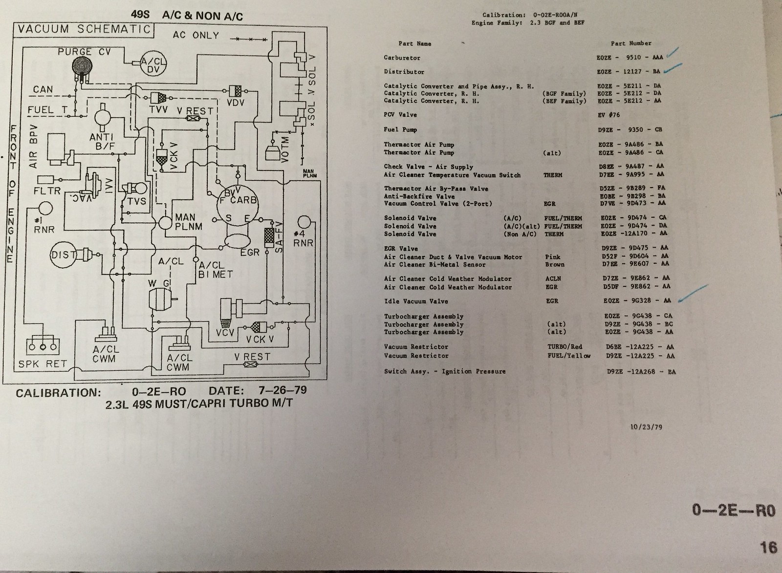
Edit- based on what I am reading my VECI is now most likely 0-2E-R0 as it shows dual SOLV, SPK-RET for turbo, E0ZE-AAA for carb which my tag shows (although the VECI adds 9510 vs. my carb 8957 tag stamped on base & 8510 raised front) and is listed for 49 State. It also is a match for my Distributor, Carb and IVV part numbers so I'm going to roll with this unless I find anything different!
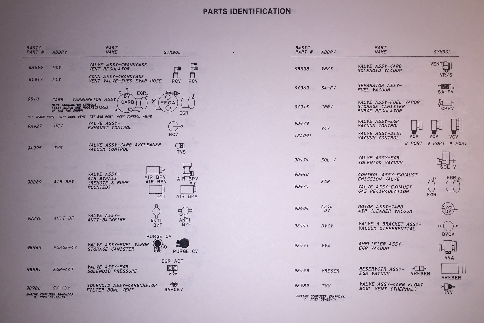
Consolidated parts ID
BTW this book covers all engines from 1980 if you can't find yours listed on myzephyrs.com site...
Last edited by m81mclaren; 01-29-2019 at 08:25 PM.
Current FEP:
1980 M81 McLaren Carb Turbo 2.3T #003P ... IT'S ALIVE after a 22 year slumber thread!
Past FEP:
1986 Capri GS 5.0- very missed but in goods hands
1985 LTD SSP- quick little fox 5.0
http://vb.foureyedpride.com/showthre...e-(carb)/page2
pacecartodd's
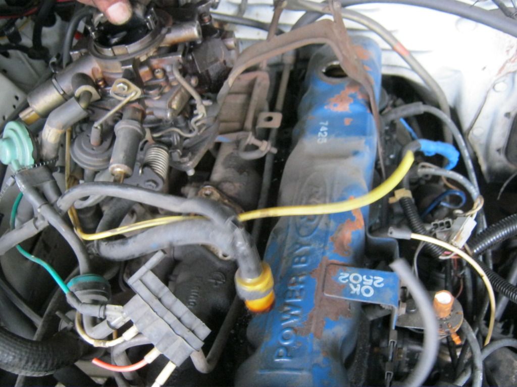
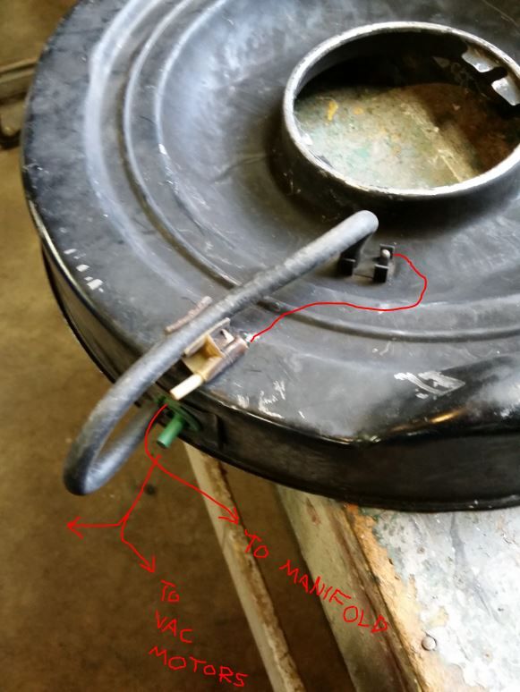
Fords 9C369 SA-FV Separtor Assembley Fuel- Vacuum
Red and yellow lines are standard vac lines for Manifold and Distibutor, respectively.
VCV,
VDV, and the turquois line is really Blue = effectively, some kind of defacto Throttle Kicker control.
It could do it a number of ways, effectively behaving as a means of sustaining vacuum under step off.
It may use the the heater vent suction control or the Horsepower Screw.
The way it was done on the later 1981 Fords was much more simple.
Hopefully this will give you an ah-ha moment.
Yellow line to distributor
Red to Manifold
Purge lines you have to follow through
Last edited by xctasy; 02-20-2019 at 03:32 PM.
About Respect https://www.youtube.com/watch?v=2bk9WG8KWW0
X's Album http://vb.foureyedpride.com/album.php?albumid=2922
Oz JPS Stang http://www.nzmustang.com/Images/Hist...cecars/jps.htm
4V (A)US Race V8's https://www.youtube.com/watch?v=Tqk18A-ibjA
ITZOLD 81 Fox http://vb.foureyedpride.com/showthre...-fun-and-games
6V i6's @ http://www.xecltd.info/?rd=10 ; AWD i6's @ http://www.apetracing.co.nz/
113 mph 84 5.0 at Amaroo https://www.youtube.com/watch?v=iTezv3Pzdls&t=8s
Techno KCM Loop Out: Severed Heads 1m³ Angels 1985 https://youtu.be/Wll6G1KpLqQ
Future Shock https://youtu.be/rDKGkWU0lWQ
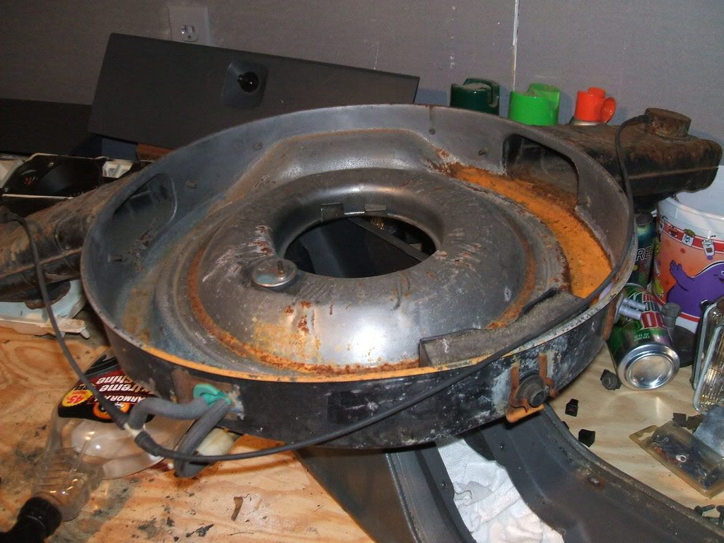
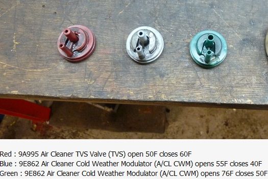
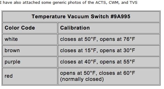
Thanks again X! I'm down to the last item on my list of needs to complete the full setup for my Anti Backfire/Air BPV/SOLV. I am looking for a red 9A995A TVS Temperature Vacuum Switch and a clip that attaches it to the air cleaner housing. Does anyone have a spare from their "deletion" pile?! I believe this will solve the backfire I'm getting when I shift gears under full throttle and will also get me through the Smog visual check.
Goes here
From the 5k mi car
looks like this crunchy one on ebay:

Current FEP:
1980 M81 McLaren Carb Turbo 2.3T #003P ... IT'S ALIVE after a 22 year slumber thread!
Past FEP:
1986 Capri GS 5.0- very missed but in goods hands
1985 LTD SSP- quick little fox 5.0
TuxStang's TVS CWM CWM Truncated
NPD lists one for twenty four ping. Depending on color, it depends on what its called.
"VALVE ASSY, CARBURETOR AIR CLEANER VACUUM CONTROL, TVS VALVE, W/ ID CODES *D7EE-9A995-AA*, *777F-9A995-BA*, ORIGINAL, D7FZ-9A995-A
Ford Mustang Years:
1979 (79), 1980 (80), 1981 (81), 1982 (82), 1983 (83)"
The tempered steel clip is from any white, pink, green or red TVS from the air cleaner.
A new Red one will impress the heck out of your Smog Man....
see fgross2006 for his ebay gotten item back in 2016.
http://vb.foureyedpride.com/showthre...42#post1863142
Here's a green one from 85MUSTANGTGT's CFi 5.0 HO .... Wilson's 83 5.0 4v SROD had the same part
About Respect https://www.youtube.com/watch?v=2bk9WG8KWW0
X's Album http://vb.foureyedpride.com/album.php?albumid=2922
Oz JPS Stang http://www.nzmustang.com/Images/Hist...cecars/jps.htm
4V (A)US Race V8's https://www.youtube.com/watch?v=Tqk18A-ibjA
ITZOLD 81 Fox http://vb.foureyedpride.com/showthre...-fun-and-games
6V i6's @ http://www.xecltd.info/?rd=10 ; AWD i6's @ http://www.apetracing.co.nz/
113 mph 84 5.0 at Amaroo https://www.youtube.com/watch?v=iTezv3Pzdls&t=8s
Techno KCM Loop Out: Severed Heads 1m³ Angels 1985 https://youtu.be/Wll6G1KpLqQ
Future Shock https://youtu.be/rDKGkWU0lWQ
If you are getting a used or new one, its best to check the 50 F open, 60 F closed figure.Very importantly, its Normally Closed.
The turbo 2.3 Carb engine takes a 227 cfm carb designed for a 2.3 engine making 88 hp, then sucks underneath the carb another 50% more air by the operation of the turbo, so its operating under 335 cfm worth of flow at wide open throttle to make 132 hp. If the boost ratio is turned up to 11 psi, then the carb is asked to flow 400 cfm. Those vacuum switches have to be 100% correct, or it'll close off the power valve, and excessively lean out the engine. Whihc is probably what has been happening under a savage Wide Open Throttle, or a quick step off on the accelerator pedal.
JACook noted that the Truck F150/250/350's in 5.8 HO form had a white TVS to ensure the power valve wasn't prevented from opening under wide open throttle. The Red TVS does the same thing for a draw through Turbo 2.3.
cf this TVS rating blurb from Luke76:-
Just be very aware Red TVS is not listed here below in JACook's post, but the details above are correct, and its operation and specfications are generally supplied, and its color governs its name.TVS, CWM or ACTS
Last edited by xctasy; 02-22-2019 at 08:27 PM.
About Respect https://www.youtube.com/watch?v=2bk9WG8KWW0
X's Album http://vb.foureyedpride.com/album.php?albumid=2922
Oz JPS Stang http://www.nzmustang.com/Images/Hist...cecars/jps.htm
4V (A)US Race V8's https://www.youtube.com/watch?v=Tqk18A-ibjA
ITZOLD 81 Fox http://vb.foureyedpride.com/showthre...-fun-and-games
6V i6's @ http://www.xecltd.info/?rd=10 ; AWD i6's @ http://www.apetracing.co.nz/
113 mph 84 5.0 at Amaroo https://www.youtube.com/watch?v=iTezv3Pzdls&t=8s
Techno KCM Loop Out: Severed Heads 1m³ Angels 1985 https://youtu.be/Wll6G1KpLqQ
Future Shock https://youtu.be/rDKGkWU0lWQ
Interesting calculations on the turbo carb cfm flows, X!
Adding a note:
My 79 has turbo carb tag D9ZE-MD
Specs from 1979 Ford Car Performance Specifications booklet:
Throttle bores P=32mm, S= 36mm. Same as N/A carbs.
Both turbo and n/a carbs have 27mm secondary venturis.
However, turbo carb primary venturi size differs from n/a.
Turbo primary is 26mm, n/a primary is 22mm. Easy to see the diff visually looking down the 'troat.
Due to the larger primary venturi, read spec is 270 cfm for turbo carbs.
A turbo carb is different from n/a, but looks like any other 5200 at quick glance.
Closely check for correct sizes, ports, and calibration parts internally when replacing the oe carb with rebuilt, etc.
True dat.
To clarify.
The standard Holley Weber 5200 series carb (Holley G180, any of the 1970-1979 versions, any of the other handed mirror image 1970- currnet Weber 32/36's as well), they were always a 225 to 230 cfm carb measured at 1.5" Hg or 20.3" of water pressure drop.
The other 52XX/62XX/65XX Chevette/Vega/K car versions have other venturi sizes, and other ratings.
For all non turbo Ford 2 and 2.3 liter OHC's until the 1980-82 model year downgrades, they were standard primary was 26 mm, secondary, 27 mm. In 1980, Ford USA downgraded the non turbo carb to a 22 mm primary venturi, and it lost CFM.
Elseware Fords European version of the 2-bbl Weber version stayed a 26/27 venturi carb till the end of production in South African Ford P-100's. USA, Canada and South America were alone in downgrading the Holley Weber. It got replaced by the 1-bbl Carter YFA in 1983, rated at a dismal 195-200 cfm at 3" Hg with just one approx 33 mm choke venturi.
The 1970-1979 FoMoCo Holley Weber 270 cfm rating is at 2" Hg, a reading contrived because the other 350/500/650 Holley 2-bbls are all rated at 3" Hg.
The 1980 model year non turbo downgrade wiped off 19 cfm from primary carb flow at 2"Hg, or made it a 250 cfm carb the way Holley USA rated it. The Holley Weber rating is in line with the way the industiry looked to be heading in 1970. Impco Gas and Autolite/Motorcraft and Carter were suggesting a 2 inches of Mercury rating for 4 cylinder 2-bbl carbs. That was not consistant with the traditional 3" Hg 1 -bbl and 2-bbl and 1.5" Hg 4-bbl ratings Holley used. Holley decided to consistantly report the Holley Weber versions at 2" Hg, and all the Holley books use that rating system for the Weber based 5200/5210/5220/6200/6210/6500/6520.
By 1980, the Holley 5740 or so called Carter Weber is just a European Escort carb made in the USA. In this instance, they rated it at 1.5"Hg, or just 180 cfm.
About Respect https://www.youtube.com/watch?v=2bk9WG8KWW0
X's Album http://vb.foureyedpride.com/album.php?albumid=2922
Oz JPS Stang http://www.nzmustang.com/Images/Hist...cecars/jps.htm
4V (A)US Race V8's https://www.youtube.com/watch?v=Tqk18A-ibjA
ITZOLD 81 Fox http://vb.foureyedpride.com/showthre...-fun-and-games
6V i6's @ http://www.xecltd.info/?rd=10 ; AWD i6's @ http://www.apetracing.co.nz/
113 mph 84 5.0 at Amaroo https://www.youtube.com/watch?v=iTezv3Pzdls&t=8s
Techno KCM Loop Out: Severed Heads 1m³ Angels 1985 https://youtu.be/Wll6G1KpLqQ
Future Shock https://youtu.be/rDKGkWU0lWQ
Quite a story this engine has generated. The external tech part is mind boggling as any.
Complicated but interesting to sift thru trying to put 2+2 together. Verifying parts and function (individual and overall relating) is challenging.
Someday current ecoboost tc owners may go thru the same. Good luck to them.
Has been said before older engines were easier to work on. Sure, up to a point. The last mile (engine tuning with so many emissions items) is a tough go.
Credit to Ford engineers to have built in a fail safe forgiving mode or something, that has gotten me and others down the road this far with alternate fixes and less items functioning as intended. Mine started and ran fine today, without every smog or drive-ability part operating in unison, as back in 1980.
Thanks guys for helping so much and sharing your knowledge. Interesting indeed! Once I put in this TVS and some last fine tuning I’m going to call it good. My plan is to not drive this at 10/10 and to hold boost at the 6-7 psi level and keep my hands off the fun dial in the cabin. There’s just too many things that could send this car lean in even the best conditions and it’s unclear what subtle modifications were done by McLaren Engines to be able push the limits safely to make it worth the risk going beyond. It’s pretty peppy now and I’d like to get through Smog so my son and I can finally start enjoying driving and showing it this year. There are a lot of jobs still left to do and I’m sure more surprises in store to learn from!
Current FEP:
1980 M81 McLaren Carb Turbo 2.3T #003P ... IT'S ALIVE after a 22 year slumber thread!
Past FEP:
1986 Capri GS 5.0- very missed but in goods hands
1985 LTD SSP- quick little fox 5.0
Sounds like a good idea to leave it be for a while. time to enjoy the work done, the car, and new memories.
Getting it reliable, dependable, clean running, correct running, is the major battle to be won.
Once driving it and getting to know it, solid baseline config established, can always go into it again and do a 'what if?'.
Changing one thing at a time and noting any result. Plus over time, we learn more. Sure has helped me to refocus and learn more.
Like me, with the bigger carb experiment. Carb adapter/spacer mod is progressing nicely, slowly but surely.
Spreading out a weekend's worth of work over span of months. No hurry, no mistakes (hopefully).
With no cutting or permanent mods to the stock setup or irreplaceable parts, can always go back quickly to dependable stock config.
Is cool to share info, comforting to know there are others with same type of engines out there and desire to have fun with them as intended..
Great idea.
As both you and gr79 know, its a stock 17.4 second 1/4 mile car, enough spank for today's driving conditions. M81, people are always gonna want to know....What The Heck is That!
Enjoy!
About Respect https://www.youtube.com/watch?v=2bk9WG8KWW0
X's Album http://vb.foureyedpride.com/album.php?albumid=2922
Oz JPS Stang http://www.nzmustang.com/Images/Hist...cecars/jps.htm
4V (A)US Race V8's https://www.youtube.com/watch?v=Tqk18A-ibjA
ITZOLD 81 Fox http://vb.foureyedpride.com/showthre...-fun-and-games
6V i6's @ http://www.xecltd.info/?rd=10 ; AWD i6's @ http://www.apetracing.co.nz/
113 mph 84 5.0 at Amaroo https://www.youtube.com/watch?v=iTezv3Pzdls&t=8s
Techno KCM Loop Out: Severed Heads 1m³ Angels 1985 https://youtu.be/Wll6G1KpLqQ
Future Shock https://youtu.be/rDKGkWU0lWQ

Hi everybody,
I didn't want to start a new thread because most of the questions regarding vacuum lines are answered here. I spend hours analyzing my car and comparing it to many diagrams and I am now sure that there might be some lines not correctly connected. I was able to figure most lines out thanks to all you guys whole posted and documented everything. I would be completly lost without you.
I want to simplify the vacuum situation and pacecartodd's configuartion looks great and seems to work great.
Currently my car runs ok I just have a bit of a rough idle that I think could come from a faulty vacuum line connection. And I am not sure whether my car has as much power as it should. Sadly I do not have any comparasion. However I think cleaning up the engine bay will make everything much easier...
I have mainly just 2 questions:
1. Should I connect the big vacuum line from the wastegate to the vacuum tree in the manifold or to the air cleaner?
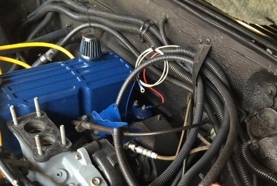
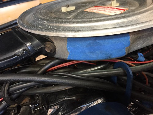
2. I have one vacuum switch that I cannot find on any other car or in any of the diagrams. (Marked in the picture) It has 3 vacuum lines and two wires.
The wires go to the spark retard thing on the other side of the engine bay.
One vacuum line goes to the air cleaner.
One vacuum line goes to the big port of the wastegate.
One vacuum line splices into the whole vacuum maze in the front of the engine.
Does anyone an idea of what that is for and how I should connect that or whether I can just completly ignore it?
One small other question... When I remove the charcoal canister is it ok to leave the fuel bowl vent of the carburetor just open and can I also leave the fuel vent line from the tank just open in the engine bay or do I need to reroute it and add some sort of filter?
Thank you!
Try the big vac hose in both spots to see what the engine likes. Air cleaner or vac tree below carb.
May have to play with carb adjustments or even timing if it was connected wrong to get things normal again.
Mine hardly runs with it connected to intake no matter what i do. (The wrong carb can make engine a dog too.)
As you prob figured out, seen that hose connected both ways.
I left the canister connected because it does not affect economy nor power.
Carb vent, tank vent. Had problems with fuel drip inside carb venturi, in hot weather, with it disconnected.
There is a wire at and under the carb vent that should be connected too.
Cant help with circled switch. Never had one like that so is unknown territory. Bet someone knows here.
Happy hunting. Found trial and error is one, maybe the only, way to sort this stuff out.
Mine runs great and desire to try and help others get theirs that way too.
Very easy to have a hose miss routed or leaking. Miles of old hose.
Guess i lucked out to get it tuned without most of it.
I connected the distributor advance to the manifold. Runs better that way. It sure don't like factory spec base timing.
A gauge would verify boost level. The green turbo light should go on at 1#.
No boost= no extra power but will run fine otherwise.
Also check vac hose connections at carb. The one on the side affects the idle on mine.
If that little hose is plugged, idles rough. Wide open-fine.
Engine is capable of idle steady between 18-20" on vac gauge at 1000 rpm. And 20+ mpg, no stalling once warmed up.
Could temp wire the choke flap wide open to see if it makes a diff. Has to get cool air too, no heat riser thing needed.
Last edited by gr79; 04-18-2020 at 04:04 PM.
Thanks gr79 for the quick answer. It seems that I just have to go via trial and error... My carb should be the correct one.
I know that the canister doesn't affect anything but I just would like to tidy everything up because right now you cannot find anything under all these vacuum lines. The wire under the carb vent is also connectedon my engine.
I do not have a boost gauge yet. But might green boost light comes only on if I accelerate quite hard.
Do you mean the venturi plug on the carb? That is capped off on mine. The choke however works fine. It opens all the way and makes no problems...
I tried to make a diagram of my current vacuum situation. I hope it is somewhat understandable
Green stuff are things that were in the diagram and also in the same place on my engine.
Yellow stuff is in the diagram but not on my engine.
Blue stuff is not in the diagram but on my engine. (the two blue X are connected I just didn't want to draw a line across the whole diagram)
Red is in the diagram and was on my engine but I removed it when I changed my exhaust manifold.
I clicked through all 107 vacuum diagrams that you guys linked here from the other site but cannot find anything that really fits. Always just some of the parts fit...
Here another picture of the weird vacuum connection on the top:

The last diagram might be a bit to overloaded with stuff and not selfexplanatory so I created a "factory style" diagram with my current setup. The vacuum lines are here somewhat accurate to where they are in the engine bay... Maybe someone can see in this one which lines are connected wrong...
Thanks again
-"Do you mean the venturi plug on the carb? That is capped off on mine. The choke however works fine. It opens all the way and makes no problems..."
http://vb.foureyedpride.com/attachme...9&d=1565718018
Post #31
This hose connection smoothed out the idle on mine. The 90 fitting in side of carb to the venturi with black/white ck valve.
Although i have boost at 4#max, reversing (flipping end for end) the smaller wastegate vac line with the check valve unlocks boost to 7#+.
A very dangerous move to do on the carb turbo engine due to 'high' compression. The EFI engines have lower comp and can run high boost.
But boy at 7# can really feel a diff like adding 20 hp or something.
Maybe next rebuild will go with the Turbo EFI's lower compression pistons and run more boost.
Have an early 79 engine 10/78. Later turbo engines seem to have different vac connections elsewhere.
One difference is the fender assy for boost. Is connected to #4 runner from the factory, not #1 per diagrams.
Same with vac advance. Moving it from carb to manifold works out much better on mine.
Most of the emissions have been removed and stored (forgot where they connected). No EGR or air pump (seized long ago).
Lots posted in http://vb.foureyedpride.com/showthre...o-vacuum-lines
http://vb.foureyedpride.com/showthre...after-15-years!
Changed the carb last year from 5200 to Holley 2300 series (2305 progressive). Boost comes on quicker, even at 1/2 pedal.
2305/80120 350 cfm carb is ultra rare but lucked out getting it. Turbo 5200 is 280 cfm and is really plenty.
Both have the throttle connection in same location. Regular 2300 have different throttle connection. And not progressive.
Did it because 5200 and especially 5200 turbo calibrated carbs are not made anymore. Finding a good one is tough.
Thing is carb turbo intake manifolds sit higher and carb flange is much closer to valve cover than n/a. Is a tight fit for bigger carbs.
However, found the different carb works very nicely once sorted out. Adapter, physical clearances, calibration, boost reference added.
No weirdness and has been dependable like the 5200. Stock engine takes 350 cfm just fine. Fuel econ is same or better.
Ok I think that this hose connection is for sure a problem on mine.
Regarding this one switch I still couldn't find what it is for but I think that it might only be on european models. Because I found some pictures of others here and they have it as well. Still waiting for replies from them though.
Wasn't the factory boost pressure something like 5#?
And with the McLaren model you could turn it up to 12# I think. With good gas, conversative timing that should still be ok or not? Would probably need an o2 sensor to make sure your not running lean...
I hope that I can figure out that one switch and than I think I understand the whole vacuum system and can fix/modify it as described by you and others.
I have a remanufactured 5200 on mine and it seems to run quite well. Maybe I will also buy a kit and try to clean and reseal the original one.
Sounds good with the other carbs. I am probably for now sticking to the remanufactured 5200 that I have but I am also wondering how well the engine would run with a Holley Super Sniper 2300 EFI on it. It is supposed to be Draw Through compatible. The regular Sniper 2300 apparently not.
Maybe would be nice but quite expensive and much more work needed to make it fit and run.
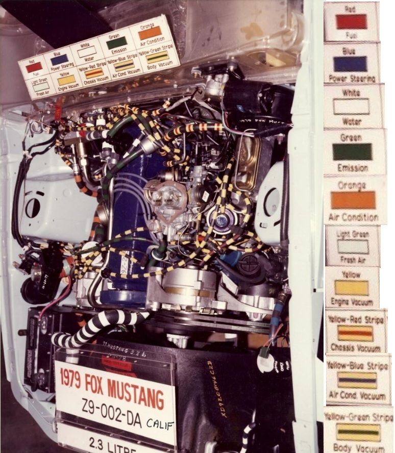
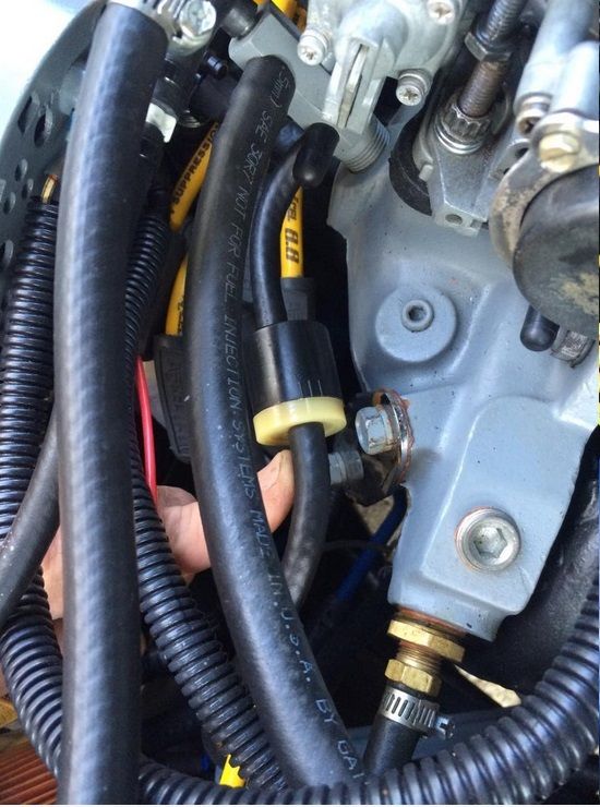
It is the same color as the Evap purge, greenish blue (teal/ turquoise), and it has an additional yellow color which is most likely the distributor color code, but may have been a repurposed TAD/TAB for the upstream and downstream AIR.
Ford color coded the parts, and as all European market cars didnt use the standard 1979 under transmission/ gearbox catalyst, then there were also some subtle other changes performed by Ford Advanced Vehicles for European sale. The DSO number would have defined some post sale changes.
The item is switched with a SOL V and the supply wire is brown with a yellow stripe, so it will be to control vacuum back to tge Heating and Ventilation Vacuum shutoff. M81 McLaren had a similar kind of issue wuth his TAD/TAD and Purge CV valves. Keep checking with SuperDuty455.
The routing will be the same for all T5s or Mustangs which were destined for private European sale. AVO in Halewood did the specification modificationd to suit the Export DSO numbers in the #9*-#99 range.
Peter in Switzerland may know as well. Your not alone, and with this information, you will work out a solution.
Meela, Georgez and gregpro50 have some nice pictures on Page One.
Jack Hidely in m81mclarens full rebuild post shows the color codes on page 18.
In fact post #427 shows a turquiose line that runs to the dash, and the Purge CV valve of the same color which has a yellow vacuum line attached to it.
http://vb.foureyedpride.com/showthre...-years!/page18
Last edited by xctasy; 04-23-2020 at 09:28 AM.
About Respect https://www.youtube.com/watch?v=2bk9WG8KWW0
X's Album http://vb.foureyedpride.com/album.php?albumid=2922
Oz JPS Stang http://www.nzmustang.com/Images/Hist...cecars/jps.htm
4V (A)US Race V8's https://www.youtube.com/watch?v=Tqk18A-ibjA
ITZOLD 81 Fox http://vb.foureyedpride.com/showthre...-fun-and-games
6V i6's @ http://www.xecltd.info/?rd=10 ; AWD i6's @ http://www.apetracing.co.nz/
113 mph 84 5.0 at Amaroo https://www.youtube.com/watch?v=iTezv3Pzdls&t=8s
Techno KCM Loop Out: Severed Heads 1m³ Angels 1985 https://youtu.be/Wll6G1KpLqQ
Future Shock https://youtu.be/rDKGkWU0lWQ
Yellow equals Vacuum Advance control
Green is HVAC or Evap Charcoal canister vacuum.
Freash Air is Teal or Turquiose.
That will narrow down your options.
Everything on an Emissions era car needs a certain amount of controls. Copying PaceCar Tods or anither turbi carb 2.3 you like is a good idea only if it still works.
Last edited by xctasy; 04-23-2020 at 09:14 AM.
About Respect https://www.youtube.com/watch?v=2bk9WG8KWW0
X's Album http://vb.foureyedpride.com/album.php?albumid=2922
Oz JPS Stang http://www.nzmustang.com/Images/Hist...cecars/jps.htm
4V (A)US Race V8's https://www.youtube.com/watch?v=Tqk18A-ibjA
ITZOLD 81 Fox http://vb.foureyedpride.com/showthre...-fun-and-games
6V i6's @ http://www.xecltd.info/?rd=10 ; AWD i6's @ http://www.apetracing.co.nz/
113 mph 84 5.0 at Amaroo https://www.youtube.com/watch?v=iTezv3Pzdls&t=8s
Techno KCM Loop Out: Severed Heads 1m³ Angels 1985 https://youtu.be/Wll6G1KpLqQ
Future Shock https://youtu.be/rDKGkWU0lWQ
 Posting Permissions

 Reply With Quote
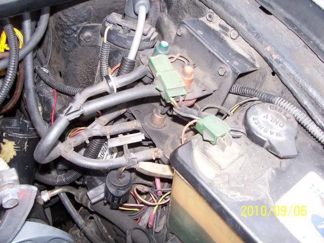


Connect With Us