
Well I sent my turbo to GPOP for a rebuild/upgrade. I hope my clocking marks somehow don't get wiped in the cleaning process as I don't have a spare like you had and it goes all bad!Originally Posted by gr79


Well I sent my turbo to GPOP for a rebuild/upgrade. I hope my clocking marks somehow don't get wiped in the cleaning process as I don't have a spare like you had and it goes all bad!
Last edited by m81mclaren; 07-17-2018 at 07:40 PM.
Current FEP:
1980 M81 McLaren Carb Turbo 2.3T #003P ... IT'S ALIVE after a 22 year slumber thread!
Past FEP:
1986 Capri GS 5.0- very missed but in goods hands
1985 LTD SSP- quick little fox 5.0
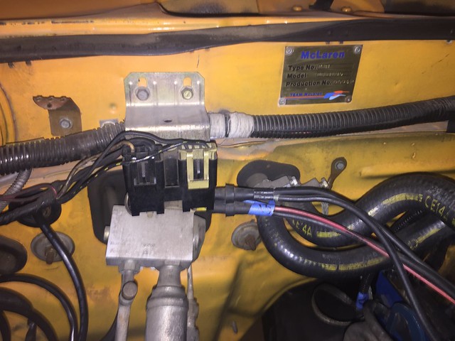
xtasy I just got confirmation of M81 car#10 also was here in CA and has the VECI sticker E0ZE-9C485-JB then BZW. My car is Federal Standard car according to my BAR sticker and door tag rather than typical California car. So I'm hoping that VECI sticker is a match to a 49 state car with A/C. Let me know if I'm on the right track and if this maps to s specific vacuum diagram I should be using!
pic of his sticker
Last edited by m81mclaren; 01-11-2019 at 03:26 PM.
Current FEP:
1980 M81 McLaren Carb Turbo 2.3T #003P ... IT'S ALIVE after a 22 year slumber thread!
Past FEP:
1986 Capri GS 5.0- very missed but in goods hands
1985 LTD SSP- quick little fox 5.0

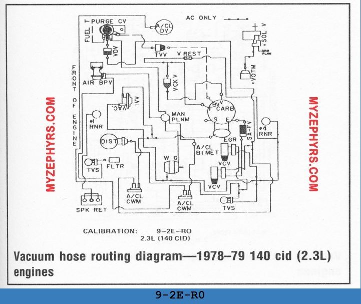
Any 1979 diagrams are close but wont match 1980 from the looks of it.
Still learning. Or relearning what was forgotten.
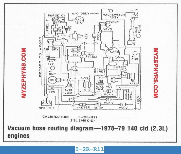
Looks like 9-2E- is 49 state. 0-01-S-R11 and 9-2R- is Calif.
A correct 1980 2.3T diagram will show a waste gate symbol (labeled W G) somewhere in the routing.
7 variations for 1979 2.3T. Mine is one of 3. Others are Calif or have different connections than mine.
One variation was the big hose at the waste gate.
Some were connected to intake manifold, some onto air cleaner (a/cl) (mine).
Engine won't run when wg big hose is connected to intake per other calibrations. Do not know why.
Eliminate diagrams with parts that do not exist on engine or contain known connections that differ.
Sorted, 1980 2.3T only diagrams (10 variations), noted differences:
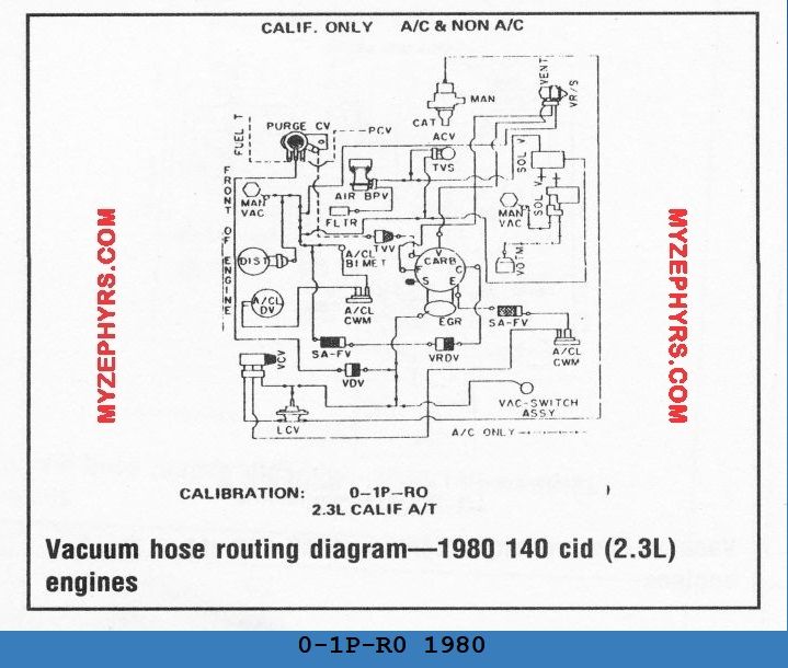
0-01H-R10 1980 (auto?) wg big hose to a/cl
0-01H-R15 1980 (auto?) wg big hose to a/cl
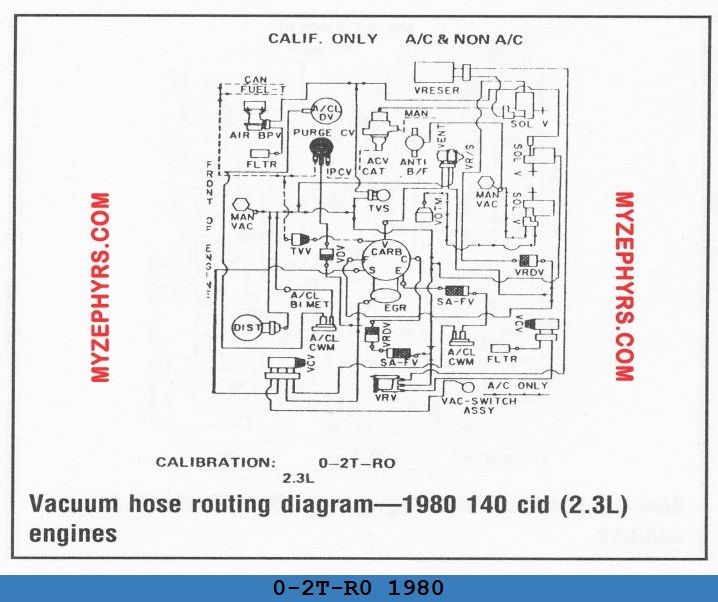
0-01S-R11 1980 (calif, auto?) wg big hose to a/cl
9-2E-R0-1980 (72) wg big hose to main plenum
9-2E-R12 1980 (73) wg big hose to main plenum
9-2E-R16 1980 (74) wg big hose to a/cl, connections to/near #4 runner
9-2E-R17 1980 (75) wg big hose to a/cl, connections to/near #4 runner
9-2E-R18 1980 (76) wg big hose to a/cl, connections to/near #4 runner
9-2R-R0 1980 (81) (calif?, single vac switch top of diagram)
9-2R-R11 1980 (82) (calif?, dual vac switchs top of diagram)
An automatic trans was available with 2.3T in 1980.
Could be auto trans are the first 3 listed with '01H' or '01S'?
Would assume extra components to keep auto trans from going wacko when shifting.
No automatic/turbo combo, no '01H' or '01S' turbo calib in 1979.
Last edited by gr79; 01-12-2019 at 01:52 AM.

Ok, thats cool. I gotcha!
And Yes gr79, you got 'em!
VECI sticker E0ZE-9C485-JB then BZW.
None of it shows up on LMR....
Your car has factory A/C.
These are the most likely ones:-
0-01H-R10 1980 40 of 107 and / or 0-01H-R15 41 of 107
It also has the following.
Spk Ret
#1RNR - No. 1 Runner (Intake Mani, metal vacuum lines)
#4RNR - No. 4 Runner (Intake Mani, metal vacuum lines)
and WG....Waste Gate!
So its 41 of 107 or 42 of 107. Click on these.
1. 0-01H-R10 1980 (40 of 107) http://myzephyrs.com/VAC_2.3/0-01H-R10%201980.html ..... Matches
2. 0-01H-R15 1980 (41 of 107) http://myzephyrs.com/VAC_2.3/0-01H-R15%201980.html Specifically 49 States..... Matches
all these aren't the ones:-
3. 0-01H-R15 1980 (42 of 107) http://myzephyrs.com/VAC_2.3/0-01H-R15%201980.html California Only ..... Not a Match
4. 0-1B-R0 1980, 43 of 107
5. 0-1B-R11 1980, 44 of 107 49 States A/C, NON A/C
6. 0-1B-R12 1980, 45 of 107 49 States A/C, NON A/C
7. 0-1G-R0 1980, 46 of 107
8. 0-21A-R0 1980, 48 of 107 49 States A/C, NON A/C
9. 0-21B-R0 1980, 49 of 107 49 States & Canada A/C, NON A/C
10. 0-2B-R0 1980, 50 of 107 49 States A/C, NON A/C
Check as well gr79's....he's got 'em!
11. 9-2E-R0-1980 (72) wg big hose to main plenum
12. 9-2E-R12 1980 (73) wg big hose to main plenum
13. 9-2E-R16 1980 (74) wg big hose to a/cl, connections to/near #4 runner
14. 9-2E-R17 1980 (75) wg big hose to a/cl, connections to/near #4 runner
15. 9-2E-R18 1980 (76) wg big hose to a/cl, connections to/near #4 runner
16. 9-2R-R0 1980 (81) (Most likely Calif?, single vac switch top of diagram)
17. 9-2R-R11 1980 (82) (Most likely Calif?, dual vac switchs top of diagram)
Last edited by xctasy; 01-12-2019 at 08:20 PM.
About Respect https://www.youtube.com/watch?v=2bk9WG8KWW0
X's Album http://vb.foureyedpride.com/album.php?albumid=2922
Oz JPS Stang http://www.nzmustang.com/Images/Hist...cecars/jps.htm
4V (A)US Race V8's https://www.youtube.com/watch?v=Tqk18A-ibjA
ITZOLD 81 Fox http://vb.foureyedpride.com/showthre...-fun-and-games
6V i6's @ http://www.xecltd.info/?rd=10 ; AWD i6's @ http://www.apetracing.co.nz/
113 mph 84 5.0 at Amaroo https://www.youtube.com/watch?v=iTezv3Pzdls&t=8s
Techno KCM Loop Out: Severed Heads 1m³ Angels 1985 https://youtu.be/Wll6G1KpLqQ
Future Shock https://youtu.be/rDKGkWU0lWQ
There are 9 possibilities.
40. 41, 72-78, and 81,82.
Anything California won't be an option.
Note that 11 to 17 (72-78, 81,82) are laid out differently to 1, 2 (40,41).
The check valves differ, and single.dual vac switches.
It could be the C3 auto option for the year are 40 and 41. TuxStang discussed this, as he checked the diagrams on line, and found the differences.
I did a screen dump of the pictures way back in 2013. 1980 2.3T Cobra DSO 89. The details are that he used were 9-2E-R93, a '79 49-state routing (without A/C)
c.f.
Last edited by xctasy; 01-12-2019 at 08:57 PM.
About Respect https://www.youtube.com/watch?v=2bk9WG8KWW0
X's Album http://vb.foureyedpride.com/album.php?albumid=2922
Oz JPS Stang http://www.nzmustang.com/Images/Hist...cecars/jps.htm
4V (A)US Race V8's https://www.youtube.com/watch?v=Tqk18A-ibjA
ITZOLD 81 Fox http://vb.foureyedpride.com/showthre...-fun-and-games
6V i6's @ http://www.xecltd.info/?rd=10 ; AWD i6's @ http://www.apetracing.co.nz/
113 mph 84 5.0 at Amaroo https://www.youtube.com/watch?v=iTezv3Pzdls&t=8s
Techno KCM Loop Out: Severed Heads 1m³ Angels 1985 https://youtu.be/Wll6G1KpLqQ
Future Shock https://youtu.be/rDKGkWU0lWQ
You guys are truly awesome!!!Thanks so much I will be studying these and trying to apply to my car. Once I feel good I'll tune the carb (and study how to adjust idle since apparently i can't find that idle screw anywhere!) and see how it impacts the AFR's until it looks in a good zone then head in to the BAR for a smog review and hopefully a test.
Current FEP:
1980 M81 McLaren Carb Turbo 2.3T #003P ... IT'S ALIVE after a 22 year slumber thread!
Past FEP:
1986 Capri GS 5.0- very missed but in goods hands
1985 LTD SSP- quick little fox 5.0
Arthur Conan Doyle Quotes....
How often have I said to you that when you have eliminated the impossible, whatever remains, however improbable, must be the truth?
There is nothing more deceptive than an obvious fact.
It is a capital mistake to theorize before one has data. Insensibly one begins to twist facts to suit theories, instead of theories to suit facts.
.
Every one of the 35000 or so 1979 to 1980 2.3 Turbo's are an indelible back-up of the VECI diagrams....The M81, the most important.
Keep at it. Compare the 9 diagrams.....diligently.
Last edited by xctasy; 01-12-2019 at 08:50 PM.
About Respect https://www.youtube.com/watch?v=2bk9WG8KWW0
X's Album http://vb.foureyedpride.com/album.php?albumid=2922
Oz JPS Stang http://www.nzmustang.com/Images/Hist...cecars/jps.htm
4V (A)US Race V8's https://www.youtube.com/watch?v=Tqk18A-ibjA
ITZOLD 81 Fox http://vb.foureyedpride.com/showthre...-fun-and-games
6V i6's @ http://www.xecltd.info/?rd=10 ; AWD i6's @ http://www.apetracing.co.nz/
113 mph 84 5.0 at Amaroo https://www.youtube.com/watch?v=iTezv3Pzdls&t=8s
Techno KCM Loop Out: Severed Heads 1m³ Angels 1985 https://youtu.be/Wll6G1KpLqQ
Future Shock https://youtu.be/rDKGkWU0lWQ
Lunch break: When you list dual vacuum solenoid in the upper section of the diagram, that must be this unit right? Are both to assist with boosting idle (one for when you turn the A/C on and the other for boosting idle if it drops too low)? If the same on my VW Rabbit its called an idle boost valve.
Since I have dual SOL V's on my firewall I can eliminate these from GR since they show a single SOL V right?
11. 9-2E-R0-1980 (72) wg big hose to main plenum (has a single SOL V)
12. 9-2E-R12 1980 (73) wg big hose to main plenum (has a single SOL V)
13. 9-2E-R16 1980 (74) wg big hose to a/cl, connections to/near #4 runner (has a single SOL V)
14. 9-2E-R17 1980 (75) wg big hose to a/cl, connections to/near #4 runner (has a single SOL V)
15. 9-2E-R18 1980 (76) wg big hose to a/cl, connections to/near #4 runner (has a single SOL V)
and also
16. 9-2R-R0 1980 (81) (calif?, single vac switch top of diagram) (has a single SOL V)
17. 9-2R-R11 1980 (82) (calif?, dual vac switch top of diagram) (has a single SOL V)
Am I on the right track? If so then on that basis I looked through all 107 diagrams listed on myzephyrs.com and only found three that have the SPK RET, Dual SOL V, and a W G. Two are the same XTASYs suggested:
1. 0-01H-R10 1980 (40 of 107) http://myzephyrs.com/VAC_2.3/0-01H-R10%201980.html ..... Matches (dual SOL V)
2. 0-01H-R15 1980 (41 of 107) http://myzephyrs.com/VAC_2.3/0-01H-R15%201980.html Specifically 49 States..... Matches (dual SOL V)
and then I see 0-01S-R11 1980 (42 of 107) http://myzephyrs.com/VAC_2.3/0-01S-R11%201980.html CALIF ONLY AC & non-AC (dual SOL V)- maybe the BAR process made them convert, I will see how it compares.
I can't tell the difference between #40 and #41. Will study up on these 3 and see if I can trace the routing. I need to learn what each of these listed things are and what they do. A while ago I started going online to parts stores to see if I can match a picture of each device to get a visual. Need to find that and if I do will post up here unless you would prefer I do it somewhere else! Thanks again so much for the invaluable help. I also owe a contribution to myzephyrs.com for posting up all these diagrams.
Last edited by m81mclaren; 01-15-2019 at 03:54 PM.
Current FEP:
1980 M81 McLaren Carb Turbo 2.3T #003P ... IT'S ALIVE after a 22 year slumber thread!
Past FEP:
1986 Capri GS 5.0- very missed but in goods hands
1985 LTD SSP- quick little fox 5.0
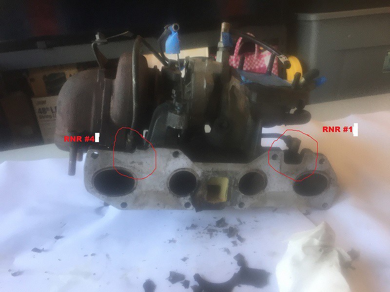
Also can someone confirm I have RNR4 and RNR1 ID'd correctly here:
If so then RNR1 is the metal pipe that turns to rubber that I have put a golf tee in that I have been trying to identify for a while. Looks like I have my SPK RET line unit incorrectly run!
This one...
Edit-Oh boy I just back tracked and see GR of course already told me this in post 336.
Last edited by m81mclaren; 01-15-2019 at 08:34 PM.
Current FEP:
1980 M81 McLaren Carb Turbo 2.3T #003P ... IT'S ALIVE after a 22 year slumber thread!
Past FEP:
1986 Capri GS 5.0- very missed but in goods hands
1985 LTD SSP- quick little fox 5.0

For those looking for the correct vacuum diagram for their cars, the best way is to use the sticker that is on the engine like I explain here.
http://myzephyrs.com/calibration_number.htm
And if you want to know what the rest of those letters and numbers on that sticker mean, that is here.
http://myzephyrs.com/engne_label_decode.jpg
Lots of FREE F/Z info on my site.
http://myzephyrs.com
Hi Red thanks for the info and the great help with the vacuum diagrams! Where is the engine sticker typically located? Is this it on the timing belt cover?
Current FEP:
1980 M81 McLaren Carb Turbo 2.3T #003P ... IT'S ALIVE after a 22 year slumber thread!
Past FEP:
1986 Capri GS 5.0- very missed but in goods hands
1985 LTD SSP- quick little fox 5.0
Yes, that is it. On 6-8 cylinder cars it is on the valve cover.
Lots of FREE F/Z info on my site.
http://myzephyrs.com
Those are the ones to focus on!
As in interim measure, Regards non adjustable idle speed, factory set like many emissions era carbs (my 1974 Pinto engined 32/36 Weber carb Mark III Ford Cortina and another 32/36 Weber conversion to a British spec formerly CDS150 1973 Hilman Hunter 1725...these both had nonadjustable idle speed carbs.
I just used an old kind of now illegal in New Zealand "nail-in aluminum light cable wall holder" or "nailed aluminum wall wire hanger".
It was a fold-able aluminum version of the Home depot clip, and the malleable metal acted as a safe spacer to bump up the curb idle if needed.

eg " EZ-Cable Clips for Exterior, White, Aluminum (15-Pack)"
You cut it short, and use the hole to create a locked in spacer that won't move or get jambed. Use at your own risk, but it worked for me.
Last edited by xctasy; 01-16-2019 at 12:56 PM.
About Respect https://www.youtube.com/watch?v=2bk9WG8KWW0
X's Album http://vb.foureyedpride.com/album.php?albumid=2922
Oz JPS Stang http://www.nzmustang.com/Images/Hist...cecars/jps.htm
4V (A)US Race V8's https://www.youtube.com/watch?v=Tqk18A-ibjA
ITZOLD 81 Fox http://vb.foureyedpride.com/showthre...-fun-and-games
6V i6's @ http://www.xecltd.info/?rd=10 ; AWD i6's @ http://www.apetracing.co.nz/
113 mph 84 5.0 at Amaroo https://www.youtube.com/watch?v=iTezv3Pzdls&t=8s
Techno KCM Loop Out: Severed Heads 1m³ Angels 1985 https://youtu.be/Wll6G1KpLqQ
Future Shock https://youtu.be/rDKGkWU0lWQ
Its a moderate long shot, but try contacting Sellis1012
SOL V has to be in those two parts. In diagrams 40, 41 and 42 of 107. There is an additional VOTM kicker idle speed adjustment, which will need to be hooked up too.
The general order of the 1980 turbo carb 2.3 control parts are still the same as 1979 turbo carb 2.3 control parts.
So this is correct.
SOL V in two part form is linked together. Ford changed it for a reason. When Ford does that, it integrates the wiring between the two items. This is a prevelent lesson with how Ford integrates wiring changes. Ford doesn't care how an single SOL V operates. A dual SOL V will operate and be wired to work only together. Ford will gender bend the pin-outs, change from normally open to normally closed, or do whatever its engineers deem to be the best solution, and they won't be thinking about how diagrams 40, 41 or 42 related to any of the others. Each electrical system is its own perfect work...
Your two part SOL V will only work if its kept together.
Last edited by xctasy; 01-16-2019 at 01:46 PM.
About Respect https://www.youtube.com/watch?v=2bk9WG8KWW0
X's Album http://vb.foureyedpride.com/album.php?albumid=2922
Oz JPS Stang http://www.nzmustang.com/Images/Hist...cecars/jps.htm
4V (A)US Race V8's https://www.youtube.com/watch?v=Tqk18A-ibjA
ITZOLD 81 Fox http://vb.foureyedpride.com/showthre...-fun-and-games
6V i6's @ http://www.xecltd.info/?rd=10 ; AWD i6's @ http://www.apetracing.co.nz/
113 mph 84 5.0 at Amaroo https://www.youtube.com/watch?v=iTezv3Pzdls&t=8s
Techno KCM Loop Out: Severed Heads 1m³ Angels 1985 https://youtu.be/Wll6G1KpLqQ
Future Shock https://youtu.be/rDKGkWU0lWQ
Thanks X! Where in the linkage did you install this spacer? Do you have an example you can share? Still, there has to be a way to adjust idle but I'll delay this until after I fix all my vacuum lines and then re-adjust timing. There's also the matter of the boost adjuster in the cabin and my SW boost gauge which is inop at the moment. There could be vacuum leak in those add-ons as well as changes to the vacuum diagrams I'll need to figure out.
Last edited by m81mclaren; 01-17-2019 at 11:21 AM.
Current FEP:
1980 M81 McLaren Carb Turbo 2.3T #003P ... IT'S ALIVE after a 22 year slumber thread!
Past FEP:
1986 Capri GS 5.0- very missed but in goods hands
1985 LTD SSP- quick little fox 5.0
Thanks Red, my sticker is faded out as you can tell in the pic but will focus on your vacuum setup postings 40, 41, and 42 of 107 to see if I can figure which is a match. Also in the vacuum diagrams what does the dashed line indicate (example is on the CARB the BV line to TVV is dashed). Does that mean fuel related as in BV= Bowl Vent?
Last edited by m81mclaren; 01-17-2019 at 02:14 PM.
Current FEP:
1980 M81 McLaren Carb Turbo 2.3T #003P ... IT'S ALIVE after a 22 year slumber thread!
Past FEP:
1986 Capri GS 5.0- very missed but in goods hands
1985 LTD SSP- quick little fox 5.0
Sorry I derailed this thread guys I got carried away. I moved my vacuum question work back over to my long-winded resurrection thread. I will ask some more questions here to keep this one on topic. Like:
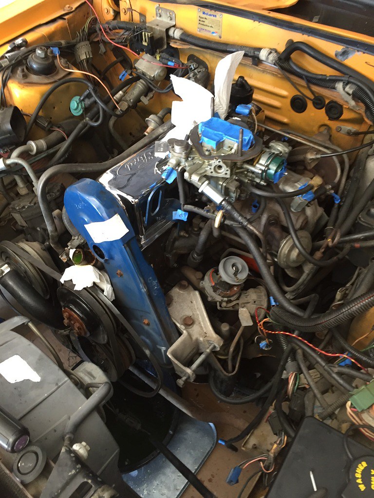
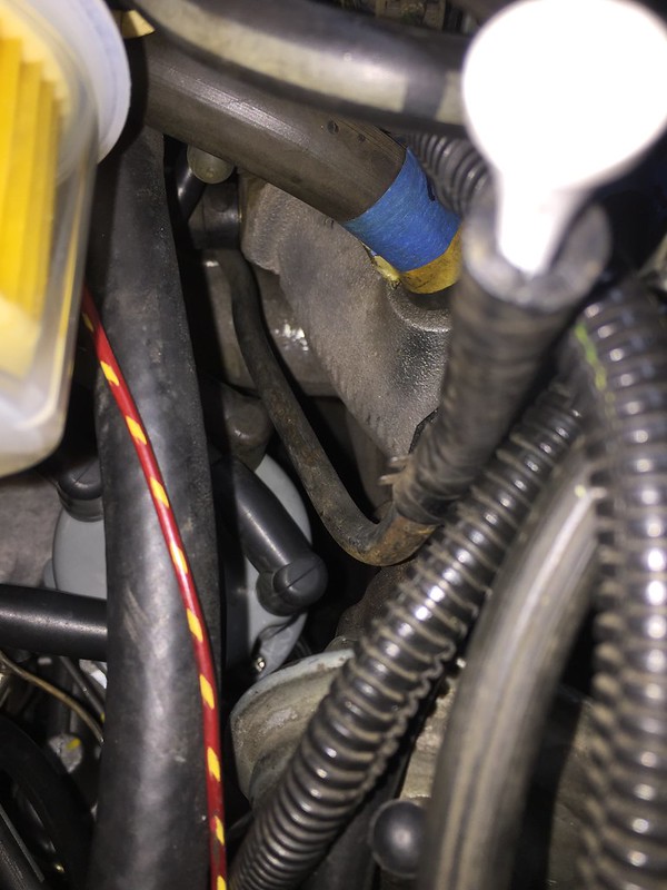
I though this was an Emissions Diverter Valve but is it actually the AIR BPV on the vacuum diagram?

Last edited by m81mclaren; 01-17-2019 at 02:55 PM.
Current FEP:
1980 M81 McLaren Carb Turbo 2.3T #003P ... IT'S ALIVE after a 22 year slumber thread!
Past FEP:
1986 Capri GS 5.0- very missed but in goods hands
1985 LTD SSP- quick little fox 5.0
We are lucky xctasy is proficient at providing details and recall.
The components are like combo lock numbers needed unlock vac routing mystery.
Could be the solenoids are part of idle control?
Looks like a/c components are nearby or connected.
If there are any part or engineering numbers on the solenoids, a google search may turn up what the exact function of the part is.
Schematic, diagram= symbolic blueprint using a symbolic way to show components and connections.
Another picture worth a thousand words (or more).
Dashed lines in vac schematic:
In electrical schematics, dashes can mean circuit is switched on/off by another component. Or an alternate connection.
Guessing similar applies in vacuum schematics where something switches flow thru hose on/off.
Have my in-car vac/boost connected to runner #4 with nylon tubing. A simple straight connection.
Mechanical type. No sending unit. Full sweep face is mechanical.
A vital gauge to monitor engine in car, especially turbocharged.
Any gauge can go bad or wear out. especially mechanical.
Am on mechanical vac/boost gauge #2 in the car. First was SW brand, current is Autometer.
Engine vacuum gauge will read steady 17"-20" at idle if everything is right.
Economy driving is 10"-18". Accelerating or load (hill) is 10"-0". Boost is positive pressure, 0"-to limit.
Deaccel (throttle off, coasting) is 20"-22" vacuum.
Possible a magnifying glass can show faint markings on the engine code sticker.
Unfortunately, is not in the ideal location, like on a bench, to do this.
Your past post on M81#10 shows that it too has a dual solenoid SOL V.
https://bringatrailer.com/listing/19...-mustang-m-81/

About Respect https://www.youtube.com/watch?v=2bk9WG8KWW0
X's Album http://vb.foureyedpride.com/album.php?albumid=2922
Oz JPS Stang http://www.nzmustang.com/Images/Hist...cecars/jps.htm
4V (A)US Race V8's https://www.youtube.com/watch?v=Tqk18A-ibjA
ITZOLD 81 Fox http://vb.foureyedpride.com/showthre...-fun-and-games
6V i6's @ http://www.xecltd.info/?rd=10 ; AWD i6's @ http://www.apetracing.co.nz/
113 mph 84 5.0 at Amaroo https://www.youtube.com/watch?v=iTezv3Pzdls&t=8s
Techno KCM Loop Out: Severed Heads 1m³ Angels 1985 https://youtu.be/Wll6G1KpLqQ
Future Shock https://youtu.be/rDKGkWU0lWQ
Yes X that's where I got the emissions sticker confirmation from and inferred that since it's 3 vin#'s from mine, also went to CA and has the dual SOLV that I'm on the right track. Appreciate the continued feedback!
Is that a AIR BPV? Are an AIR BPV and Emissions Diverter Valve the same thing?
Current FEP:
1980 M81 McLaren Carb Turbo 2.3T #003P ... IT'S ALIVE after a 22 year slumber thread!
Past FEP:
1986 Capri GS 5.0- very missed but in goods hands
1985 LTD SSP- quick little fox 5.0
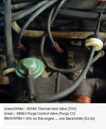
Oh boy so doing lots of internet searching trying to ID all the parts listed on the vacuum diagram for easy reference. I hope this helps others in the future as several posts by others have helped me so far. There are differences in color and parts by year but here is my 1980 2.3 Turbo built 07/80. I still have a few to ID that I can't find the name of. Please provide feedback or corrections if I am off:
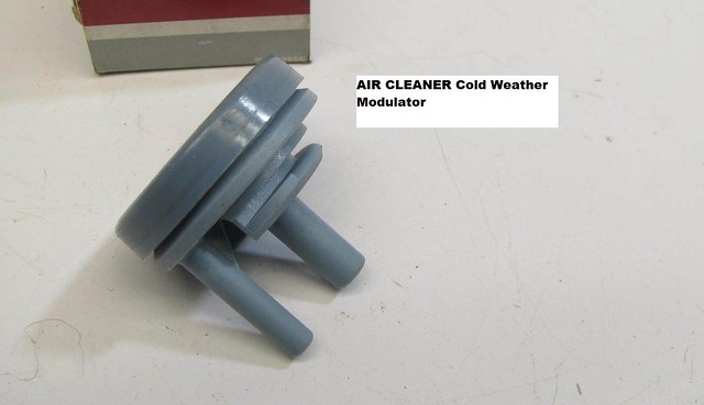
A/CLN CWW- Air Cleaner Cold Weather Modulator
AIR BPV- Thermactor (Emissions) Air Bypass Valve
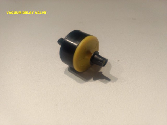
VDV Vacuum Delay Valve
VCV Vacuum Control Valve
Purge CV Purge Control Valve
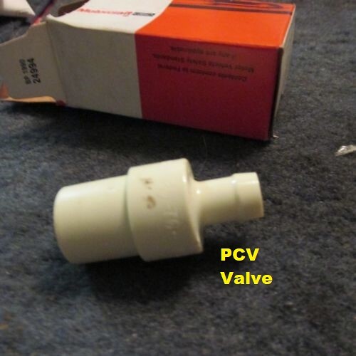
PCV Valve Positive Crankcase Vent Valve
MAN PLNM Manifold Plenum
RNR1 and RNR2 Manifold Runner 1 and 2
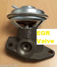
EGR Valve
SOLV Vacuum Solenoid (dual in my case but some only have one)
A/CL VCV Air Cleaner Vacuum Control Valve
A/CL BI MET Air Cleaner Temperature Sensor (? not certain this is the BI MET doodad)
[/url]
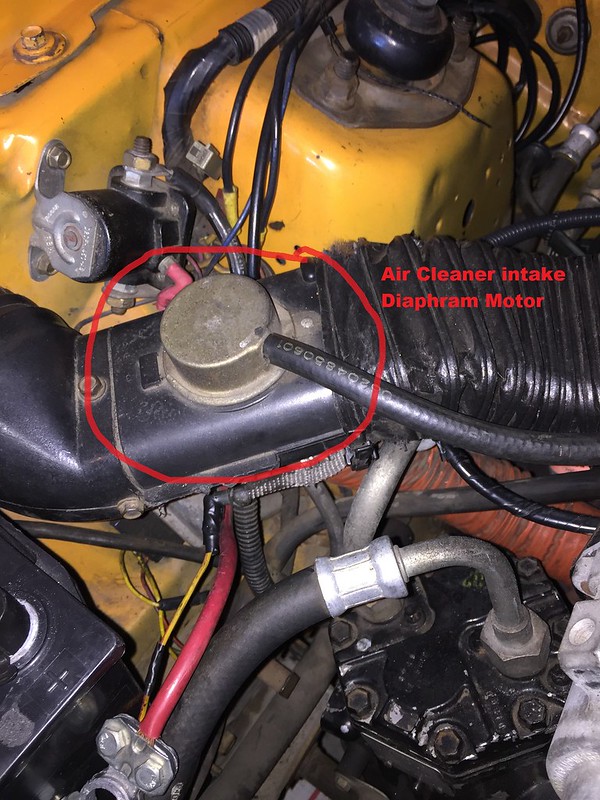
A/CL ?? Air Cleaner Intake Vacuum Diaphragm Motor
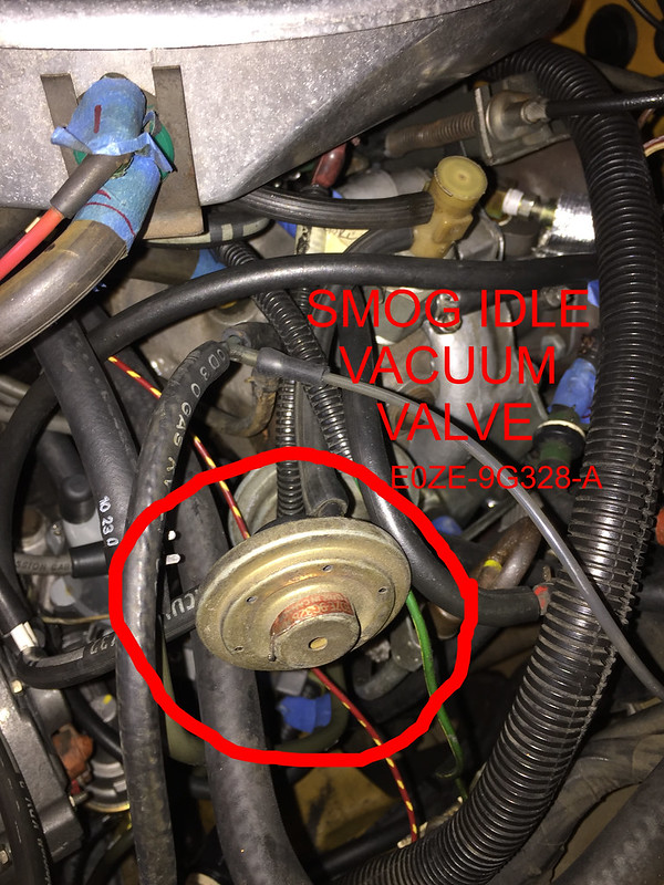
IVV Smog Idle Vacuum Valve
SPK RET Spark Retard (goes to RNR1 and helps helps with retard distributor under boost load)
This is just a start. What would be helpful are pics/location/description of the following:
A/CL DV (is this the Air Cleaner Intake Vacuum Diaphragm Motor I pictured above?)
FLTR (connects to AIR BPV)
SA FV- Separator Assembly Fuel Vacuum
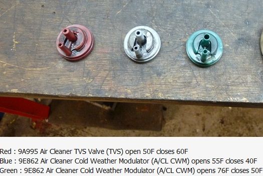
TVS- Air Cleaner TVS Valve (TVS= ? Thermal Vest Switch?)
TVV- Thermal Vent Valve
VAC IVV- Vacuum Idle Vacuum Valve
VCV- Vacuum Control Valve
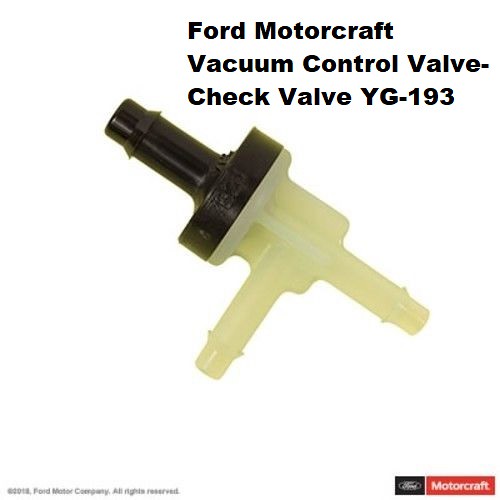
V CK V- Vacuum Check Valve
VCKV- Vacuum Check Valve
VDV- Vacuum Delay Valve
VOTM- Vacuum Operated Throttle Module
VRDV- Vacuum Retard Delay Valve
VREST- Vacuum Restrictor
Current FEP:
1980 M81 McLaren Carb Turbo 2.3T #003P ... IT'S ALIVE after a 22 year slumber thread!
Past FEP:
1986 Capri GS 5.0- very missed but in goods hands
1985 LTD SSP- quick little fox 5.0
Hang in there man. Upstream and downstream AIR and the TAB/TAD references are quite specific to only I4, I6, V6 or V8 carb variants. The IVV and AIR BPV: Air Bypass Valve differed to some later 1981 on Fords.
Many Fords got a somewhat complicated Item 53, a Carburetor Throttle Solenoid Positioner (Repeat of 34, Anti Dieseling Valve/Idle Stop Solenoid)
I have some pictures festooned in my 1981 I6 3.3 liter stuff. It'll help a little, but its jolly hard to divide and amplify the pertinent parts
http://vb.foureyedpride.com/showthre...cuum-nightmare
and
http://vb.foureyedpride.com/showthre...L-3-3L-i6-help
are a little help
By 1985, there were about 93 carb era VECI "items".
Now, you asked only for 14, but they related to about 18 items.
In order to find them, you must find them in order....
In order:-
Items 2, 7, 16, 22, 24, 26, 27, 28, 65, 66, 67, 68, 87, but also items 1, 4, 34, 53, 73
FLTR is unlisted on my pick list, but IIRC, it is an air filter paper pad which, like the sintered open vent valve such as
Item 23 VRESER: Vacuum Reservoir (Actually VRESER just stands for Vacuum Reservoir. It may or may not have a valve or Solenoid Valve inside it).
Item 76 FUEL T (VECI Diagram detail)
Item 77 SLEEVE (VECI Diagram detail)
Item 78 TO ATMOS (VECI Diagram detail)
Item 79 VAC-SWITCH ASSY (VECI Diagram detail)
is specific to your 2.3 application....
Mapped out, they are:-
Item 2 A/CL DV ( A/CL: according to Ford, that is Item 1, the air cleaner)
Item 7 AIR BPV: Air Bypass Valve (aka Thermactor Air Bypass TAB)
Item 80 SA-FV: Separator Assembly Fuel / Vacuum (VECI Diagram detail)
Item 27 TVS: Thermal Vacuum Switch, and is different to a Dashpot. On Fords these are usually located in the air cleaner. IMPORTANT: Color
defines Fords VECI Name, although clearly stamped TVS, they are called Item 4 A/CL CWM: Air Cleaner Cold Weather Modulator's and may be
Green, Purple, Grey, White, Black or Yellow with a different rating based on color.
Item 28 TVV: Thermal Vent Valve. On Fords they are mostly controlled by ambient air temps. Simular to a TVS. Located between the carb and
the charcoal canister.
Item 16 IVV: Thermactor Idle Vacuum Valve (I'd disregard the Vac part)
Item 65 VCS: Vacuum Controlled Switch
Item 66 VCS: Vacuum Controlled Switch (Cold Temp)
Item 67 VCS: Vacuum Controlled Switch (Decel Idle)
Item 22 VCKV: Vacuum Check Valve
Item 68 VDV: Vacuum Delay Valve
Item 87 VOTM : Vacuum Operated Throttle Modulator (Variation on 34 and 53 Carburetor Throttle Solenoid Positioner, 73 TK [Throttle Kicker])
Item 26 VRDV: Vacuum Retard Delay Valve, as these can be used on more than just the distributor.
Item 24 VREST: is a vacuum restriction, usually at the thermally controlled valve on top of the thermostat housing.
Okay, my first suggestion is grab your VECI and have your son apply some color by high liter!
Sadly,
Colors are:-
care of Stormin'Norman's source of color identification
Red = Main vacuum
Green = EGR function
Orange = Heat control Valve (exhaust & intake) (AKA heat riser but more complex)
YellowYellow = Distributor advance
White = EGR vacuum (source)
Black = Mainly used for the Evaporative emissions control
Brown = Thermactor ACV or Diverter valve
Blue = Throttle Kicker control
Pink = Thermactor Air Bypass Valve (BPV)
SOL V is my idle"Throttle Kicker", which is the VOTM circuit dotted.
Item 58 SOL V: Solenoid Valve ( Repeat of Item 19 SOL V: Solenoid Valve, and Item 33, Idle Boost Solenoid ), and Item 93 Vac Switch Assembly
The comprehensive list I have is:-
0 VECI: Vehicle Emission Control Information, a Diagram detail
1 A/CL: according to Ford, that IS the air cleaner
2 A/CL DV: Air Cleaner Duct & Valve
3 A/CL BI MET: Air Cleaner Bi-Metallic Valve
4 A/CL CWM: Air Cleaner Cold Weather Modulator
5 ACV: Air Control Valve
6 AIR: This is a Secondary air injection Ford calls the Thermactor, short for Thermal Reactor. CA vehicles are installed with it as standard. Air Injection Reaction is what it stands for.
The thermactor system consists mainly of the air pump, the air pump diverter and bypass valves, TAB and TAD solenoids (if equipped) and the catalytic converter.
7 AIR BPV: Air Bypass Valve (aka Thermactor Air Bypass TAB)
8 BV: Bowl Vent (on top of the float tanks)
9 CARB: Carburetor
10 CPRV: Canister Purge Valve ( PURGE CV : )
11 DIST : Distributor of course.
12 EGR: Exhaust Gas Recirculator
13 EFCA: Electronic Fuel Control Assembly (ie Central Fuel Injection or Throttle Body Injection on EECIII and EECIV CFi "EFI" Fords)
14 FLTR: Filter
15 FPR: Fuel Pressure Regulator
16 IVV: Thermactor Idle Vacuum Valve
17 MAN VAC: Indicating Manifold vacuum-Vacuum source
18 MAP: Manifold Absolute Pressure (BMAP: Bariometric Manifold Absolute Pressure, in the case of CFi 5.0 EECIII cars from 1979 to 1985)
19 SOL V: Solenoid Valve
20 SV-CBV: Carburetor Fuel Bowl Solenoid Vent Valve
21 V VAC: short for Vacuum
22 VCKV: Vacuum Check Valve
23 VRESER: Vacuum Reservoir (Actually VRESER just stands for Vacuum Reservoir. It may or may not have a valve or Solenoid Valve inside it).
24 VREST is a vacuum restriction, usually at the thermally controlled valve on top of the thermostat housing.
*On 87 4V 460 F250 truck it is a simple Blue plastic orifice inline with the vacuum line. On 81 IV 200, Pink plastic orifice inline with the vacuum line
25 VRV: Vacuum Regulator Valve
26 VRDV: Vacuum Retard Delay Valve, as these can be used on more than just the distributor.
27 TVS: Thermal Vacuum Switch, and is different to a Dashpot. On Fords these are usually located in the air cleaner. IMPORTANT: Color defines Fords VECI Name, although clearly stamped TVS, they are called Item 4 A/CL CWM: Air Cleaner Cold Weather Modulator's and may be Green, Purple, Grey, White, Black or Yellow with a different rating based on color.
28 TVV: Thermal Vent Valve. On Fords they are mostly controlled by ambient air temps. Simular to a TVS. Located between the carb and the charcoal cannister.
29 PVS: Ported Vacuum Switch: Very similar to TVVs except on Fords they are used in the cooling system and are controlled by water temps.
30 PURGE CV: Vapor Canister Purge Valve
31 EVAP CANISTER ASY
32 ISC: Ford refers to theirs as an Idle Speed Control (ISC) solenoid. Others mis-use the Idle Air Contro (IAC) term
33 Idle Boost Solenoid (Orange Knob on 81, 82, 83 A/C Equiped 3.3's) or Throttle Kicker Control (TK)
34 Carburettor Throttle Solenoid Positioner (Anti Dieseling Valve/Idle Stop Solenoid)
35 S Spark Port
36 EGR Actuator
37 E EGR Port
38 CATALYST or CAT is catalytic converter (VECI Diagram detail is CATALYST)
39 ENG is engine;
40 ACT - not sure, but on EFIs it means Air Charge Temperature sensor
41 Inlet Air Temperature Control
42 Green DVCV 2 port PVS Vaccum Switches
43 Blue TCVV 3 Port Vaccum Switches
44 Dual Diaphram Distibutor
45 Black SDV Cold Start Spark Delay valve
46 Black SDV EGR Vaccuum delay valve
47 Deceleration Valve (PVS Cold Start lockout Dampened, Non Dashpot)
48 Non dampened or 2 port PVS (dampened) control EGR
49 Attitude and Position Fuel Trap
50 PVS Vacuum with Sintered Line Filters
51 Close Limit primary or Main Jets,
52 Lead plug sealed idle screws
53 Carburetor Throttle Solenoid Positioner (Repeat of 34, Anti Dieseling Valve/Idle Stop Solenoid)
54 Evaporative Emmission Control System
55 Anti Backfire Valve
56 EGR Valve Actuator
57 Vacuum Regulator/Solenoid
58 SOL V: Solenoid Valve ( Repeat of 19 )
59 Venturi Vacuum Amplifier
60 Load Control Valve
61 EGR B/P Transducer
62 Signal Conditioner
63 Ported Pressure Switch
64 Vent Valve Vacuum
65 Vacuum Controlled Switch
66 Vacuum Controlled Switch (Cold Temp)
67 Vacuum Controlled Switch (Decel Idle)
68 Vacuum Delay Valve
69 Vacuum Vent Valve
70 Delay Valve Two Way
71 Ignition Timing Vacuum Switch
72 Ignition Pressure Switch
73 TK (Throttle Kicker)
74 Mushroom caps for charcoal fuel vapor canister vents (VECI Diagram detail).
75 CARB BV (VECI Diagram detail, Repeat of 8 BV: Bowl Vent [on top of the float tanks])
76 FUEL T (VECI Diagram detail)
77 SLEEVE (VECI Diagram detail)
78 TO ATMOS (VECI Diagram detail)
79 VAC-SWITCH ASSY (VECI Diagram detail)
80 SA-FV: Separator Assembly Fuel / Vacuum (VECI Diagram detail)
81 PCV: Positive Crankcase Ventilation (VECI Diagram detail)
82 A : Area to apply Hand Vacuum Pump test (VECI Diagram detail, often multiple 2X)
83 Anti B/F : Anti Back Fire
84 HEAT VLV : Heat Riser Valve (Drivers side Header Heat Riser in some cases)
85 HICV : Hot Idle Control Valve
86 VOLTM : Vacuum Operated Load Throttle Modulator
87 VOTM : Vacuum Operated Throttle Modulator (Variation on 34 and 53 Carburettor Throttle Solenoid Positioner, 73 TK [Throttle Kicker])
88 VR/S: Vacuum Regulator Solenoid
89 VRDM : Vacuum Retard Delay Modulator
90 DUMP : Dump (Open to Air, VECI Diagram detail)
91 DIV : Diverter (VECI Diagram detail)
92 LCV : Load Control Valve
93 Vac Switch Assembly (Like SOL V, only vac operated, Refer Item 33, Idle Boost Solenoid [Orange Knob on 81, 82, 83 A/C Equiped 3.3's] used as a kind of Throttle Kicker Control [TK], but to control base idle)
Last edited by xctasy; 01-22-2019 at 01:58 AM.
About Respect https://www.youtube.com/watch?v=2bk9WG8KWW0
X's Album http://vb.foureyedpride.com/album.php?albumid=2922
Oz JPS Stang http://www.nzmustang.com/Images/Hist...cecars/jps.htm
4V (A)US Race V8's https://www.youtube.com/watch?v=Tqk18A-ibjA
ITZOLD 81 Fox http://vb.foureyedpride.com/showthre...-fun-and-games
6V i6's @ http://www.xecltd.info/?rd=10 ; AWD i6's @ http://www.apetracing.co.nz/
113 mph 84 5.0 at Amaroo https://www.youtube.com/watch?v=iTezv3Pzdls&t=8s
Techno KCM Loop Out: Severed Heads 1m³ Angels 1985 https://youtu.be/Wll6G1KpLqQ
Future Shock https://youtu.be/rDKGkWU0lWQ
OMG my head hurts!
Current FEP:
1980 M81 McLaren Carb Turbo 2.3T #003P ... IT'S ALIVE after a 22 year slumber thread!
Past FEP:
1986 Capri GS 5.0- very missed but in goods hands
1985 LTD SSP- quick little fox 5.0
Found a few (from 1985 Emissions Diagnostic Manual Vol H). Believe they are same items or close.
Let me know if these help or need clearer pics, etc.
Gosh, it's like am back at the HF Museum to document items (went there yesterday).
Is helping me understand this stuff a little better too.
Am sure others may benefit too. Tried to title post using key words for future searches.
VREST
VRDV and VDV
VOTM
VCK, VCK-x
VCV (also commonly called ported vacuum switch). One type also has an electrical connector.

Last edited by gr79; 01-22-2019 at 05:25 PM.
(vacuum) IVV (Thermactor Idle Vacuum Valve) and TVV?
TSP-VOTM found this one that says VOTM too.
TVS
SA-FV Wonder if: SA-FA is a typo or Ford changed FV to FA?

 Posting Permissions

 Reply With Quote
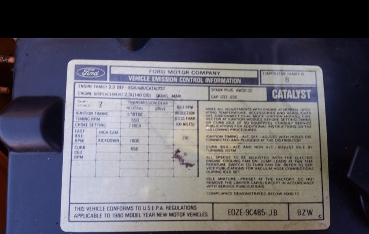


Connect With Us