Thanks. Although my components are operating in reverse to achieve the same operation.
My '83 is an early build (Oct. '82). (if that might explain the differences ?)
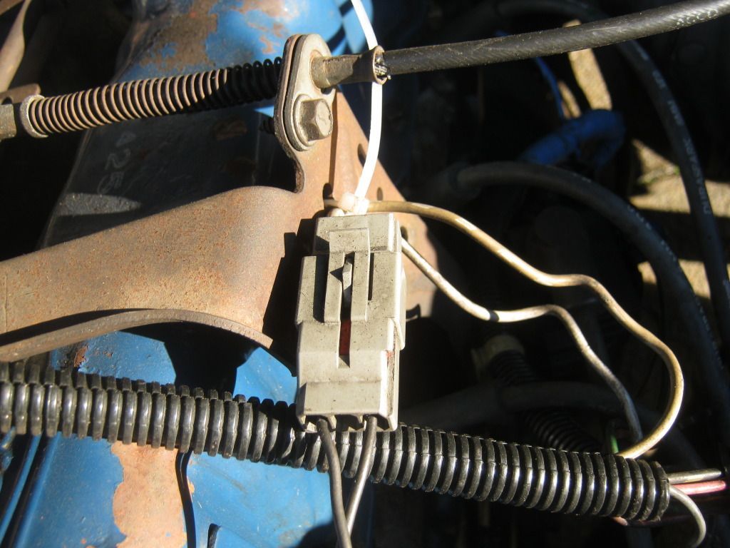
Anyway, my vacuum switch is definitely closed (13.2 ohms) at atmosphere (from 0 to 8 inches)
and the goes to open circuit with 8 inches or more.
Attachment 108554
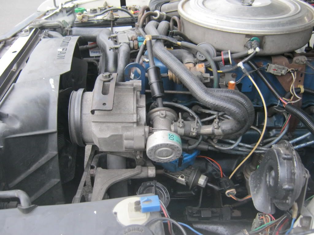
Also, my TAB and TAD solenoids "pass through" vacuum when they are not energized.
When energized the solenoids block the source vacuum and vent the "device" to atmosphere.
The end result is operation just as you described.
What is the reason to send thermactor air upstream during heavy load ?
Thanks
Todd H.


[reflist][/reflist]

 Reply With Quote


 .
. 


Connect With Us