Close


Page 2 of 3 FirstFirst 123 LastLast
Results 26 to 50 of 65
  1. #26
    FEP Super Member gr79's Avatar
    Join Date
    Jun 2009
    Location
    SE Michigan
    Posts
    5,154

    Default

    If rebuilding, inspect the housing carefully.
    Mostly around the round ft cooling hole area.
    Near the mounting ear area.
    When the housing cracks, they don't put out much..
    Had two on my 93 Ranger do that. OE #1 and used #2
    It is a side mount ear style if that matters.
    #3 is a new Remy. So far so good.

    Make sure the stator wire or plug is tight, no wiggle.

  2. #27

    Default

    Quote Originally Posted by mustangxtreme View Post
    Your alternator needs to be hooked up like this. I have had mine set up like this for over 60,000 miles.


    THIS needs the ground? I'm almost positive it isn't there. What gauge wire? Ground to chassis?


    Sent from my iPhone using Tapatalk

  3. #28
    FEP Senior Member OldsRocket442's Avatar
    Join Date
    Mar 2006
    Location
    Spanaway, Washington
    Posts
    887

    Default

    You don't need that ground. The body of the alternator grounds through the brackets it attaches to.
    Richard

    1986 Mustang LX v8 t5 conversion
    1986 Mustang LX 2.3 Auto - Acquired 2-27-13


    http://www.cardomain.com/ride/2549044

    My other "4 eye" is a '67 Cutlass

  4. #29
    FEP Senior Member danco86's Avatar
    Join Date
    Feb 2012
    Location
    British Columbia, Canada
    Posts
    731

    Default

    Reattaching the black and orange wires won't change anything. They attach via fusible links to other wires that all eventually lead back to the hot side of the starter solenoid, which is where the added 4 gauge wire lands anyways. I removed mine altogether when I did my 3G conversion. When you bought the alternator, you should have gotten the other plug in that goes into it. It has a yellow wire, white wire, and green/red wire. Two of these need to be spliced into the wires of the old 2 wire connector that plugged into the old alternator.
    Can you post a pic of those wires connected to your 3G? I see them in your first pic, but cannot tell where their connection points are.
    Lastly, that larger yellow wire you are asking about, is not to do with the charging system. It is the power wire for your rear window defroster.

    I will post pics of my wiring scheme later today.
    Last edited by danco86; 09-08-2016 at 11:27 AM.
    Dan

    http://vb.foureyedpride.com/showthre...ng-GT-restomod


    1986 Mustang GT Cobra
    Lotsa stuff, lotsa work. Check my thread above.

    Daily drivers
    2002 F-350 7.3 Powerstroke crew 4X4
    2012 F-150 Ecoboost Screw FX4

  5. #30

    Default

    I installed the 95amp alternator. Same results.


    Sent from my iPhone using Tapatalk

  6. #31

    Default

    The green/red wire turns on the alternator. Without this and the white wire, the alternator will not charge. That wiring schematic would work fine that was poster earlier, but I don't get why you would hook it to the starter signal wire instead of leaving it hooked up to the battery light like it would be from the factory.

    The yellow wire is a voltage monitoring wire. This should go back to the battery so that the alt can ramp up voltage under load, but it won't hurt anything being looped back to the input stud.

    You need the other wiring. Auto zone or any other auto parts store will have a "alt repair plug harness" or something like that in the help/Dorman section, or often with fuses or wiring, sometimes both. Then you don't even have to go hit the junkyard for an old crappy plug.
    2 1986 cougars (both 4 eyed and 5.0)
    1 1987 cougar

  7. #32
    FEP Senior Member danco86's Avatar
    Join Date
    Feb 2012
    Location
    British Columbia, Canada
    Posts
    731

    Default

    How about that pic of the wires on the back of your alt? Where is that wht/blk wire going? If both alternators aren't charging, it is more than likely than not a wiring issue to you regulator. And like mentioned earlier, set you voltmeter to the VDC range, on 20.
    The battery setting you have it on in your pics is for checking 1.5V & 9V NiCad batteries. I am guessing that you are not getting the signal to your alternator to excite the field winding to start producing voltage. But I need to see pics of your connections to tell.
    Dan

    http://vb.foureyedpride.com/showthre...ng-GT-restomod


    1986 Mustang GT Cobra
    Lotsa stuff, lotsa work. Check my thread above.

    Daily drivers
    2002 F-350 7.3 Powerstroke crew 4X4
    2012 F-150 Ecoboost Screw FX4

  8. #33

    Default

    Quote Originally Posted by danco86 View Post
    How about that pic of the wires on the back of your alt? Where is that wht/blk wire going? If both alternators aren't charging, it is more than likely than not a wiring issue to you regulator. And like mentioned earlier, set you voltmeter to the VDC range, on 20.
    The battery setting you have it on in your pics is for checking 1.5V & 9V NiCad batteries. I am guessing that you are not getting the signal to your alternator to excite the field winding to start producing voltage. But I need to see pics of your connections to tell.
    The white wire isn't spliced into anything. Goes from the plug straight to the regulator.


    Sent from my iPhone using Tapatalk

  9. #34

    Default

    The white wire needs to be spliced somewhere?

  10. #35
    FEP Senior Member danco86's Avatar
    Join Date
    Feb 2012
    Location
    British Columbia, Canada
    Posts
    731

    Default

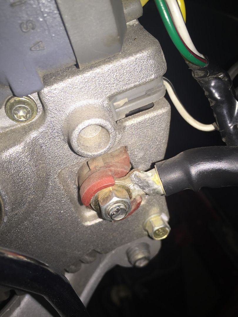
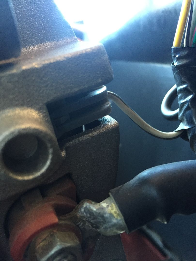
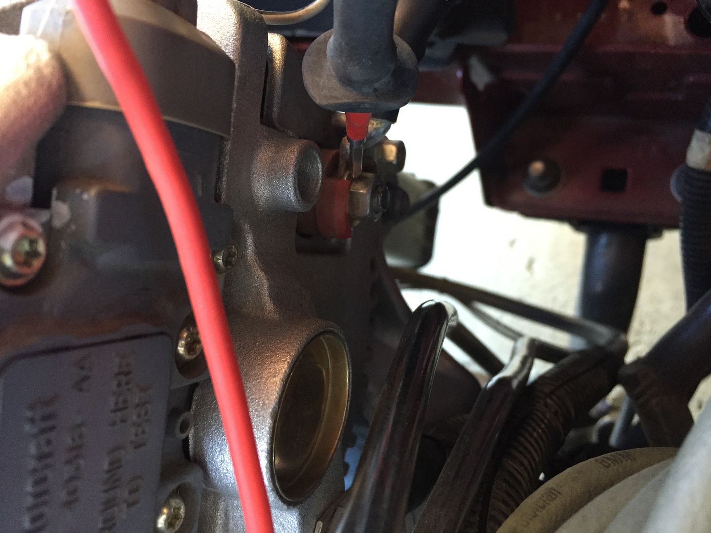
    No. It should come out of the plug marked 'S' and then plug into the back of the alternator here( grey clip):
    Last edited by danco86; 09-13-2016 at 01:24 PM.
    Dan

    http://vb.foureyedpride.com/showthre...ng-GT-restomod


    1986 Mustang GT Cobra
    Lotsa stuff, lotsa work. Check my thread above.

    Daily drivers
    2002 F-350 7.3 Powerstroke crew 4X4
    2012 F-150 Ecoboost Screw FX4

  11. #36

    Default

    That's what I got.


    Sent from my iPhone using Tapatalk

  12. #37

    Default

    Quote Originally Posted by danco86 View Post
    No. It should come out of the plug marked 'S' and then plug into the back of the alternator here( grey clip):
    danco, here is my wiring... I soldered connection behind the white tape.

    Also shown in the unused yellow wire.


    Sent from my iPhone using Tapatalk

  13. #38

    Default

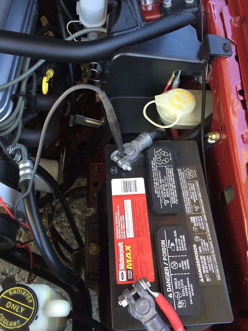
    Can I run an extra wire from the positive terminal of the battery to the lug on the alternator? Just to see if that will boost the power? In other words, jump the 4ga fused wires with a wire to see if that's the problem?

    Also, is there any possibility that the little fuseable links coming off the solenoid have gone bad?


    Sent from my iPhone using Tapatalk

  14. #39
    FEP Senior Member danco86's Avatar
    Join Date
    Feb 2012
    Location
    British Columbia, Canada
    Posts
    731

    Default

    that shouldn't do anything. Put your black meter lead on ground or battery -ve. Put the red meter lead on the +ve lug of the alternator (car not running, key not on) you should still see ~12V on the meter. You have now proved continuity between the battery and the alternator. So even if you had a bad fusible link somewhere, the alt would still charge the battery via the 4 gauge wire you have installed.
    Last edited by danco86; 09-14-2016 at 01:35 AM.
    Dan

    http://vb.foureyedpride.com/showthre...ng-GT-restomod


    1986 Mustang GT Cobra
    Lotsa stuff, lotsa work. Check my thread above.

    Daily drivers
    2002 F-350 7.3 Powerstroke crew 4X4
    2012 F-150 Ecoboost Screw FX4

  15. #40
    FEP Senior Member danco86's Avatar
    Join Date
    Feb 2012
    Location
    British Columbia, Canada
    Posts
    731

    Default

    As I mentioned earlier, that unused bigger yellow wire is the power wire for your rear window defroster. Your car has one, I assume?

    Now in your pics,the alternator is unplugged, did you unplug it for picture clarity? I can't tell for sure from the picture, but the white/black wire looks broken where it's supposed to plug into the alternator.
    I will take thorough pics of my setup in the morning for you.
    Dan

    http://vb.foureyedpride.com/showthre...ng-GT-restomod


    1986 Mustang GT Cobra
    Lotsa stuff, lotsa work. Check my thread above.

    Daily drivers
    2002 F-350 7.3 Powerstroke crew 4X4
    2012 F-150 Ecoboost Screw FX4

  16. #41

    Default

    Quote Originally Posted by danco86 View Post
    As I mentioned earlier, that unused bigger yellow wire is the power wire for your rear window defroster. Your car has one, I assume?

    Now in your pics,the alternator is unplugged, did you unplug it for picture clarity? I can't tell for sure from the picture, but the white/black wire looks broken where it's supposed to plug into the alternator.
    I will take thorough pics of my setup in the morning for you.
    No AC. No rear defroster. Doesn't have one. Never came with one. Yes I unplugged for the picture


    Sent from my iPhone using Tapatalk

  17. #42
    FEP Senior Member danco86's Avatar
    Join Date
    Feb 2012
    Location
    British Columbia, Canada
    Posts
    731

    Default

    Quote Originally Posted by congerz83 View Post
    No AC. No rear defroster. Doesn't have one. Never came with one. Yes I unplugged for the picture


    Sent from my iPhone using Tapatalk
    I guess that's why the yellow one isn't plugged into anything, then.
    Last edited by danco86; 09-15-2016 at 01:00 AM.
    Dan

    http://vb.foureyedpride.com/showthre...ng-GT-restomod


    1986 Mustang GT Cobra
    Lotsa stuff, lotsa work. Check my thread above.

    Daily drivers
    2002 F-350 7.3 Powerstroke crew 4X4
    2012 F-150 Ecoboost Screw FX4

  18. #43
    FEP Senior Member danco86's Avatar
    Join Date
    Feb 2012
    Location
    British Columbia, Canada
    Posts
    731

    Default

    Ok. Let's try checking things with your meter.

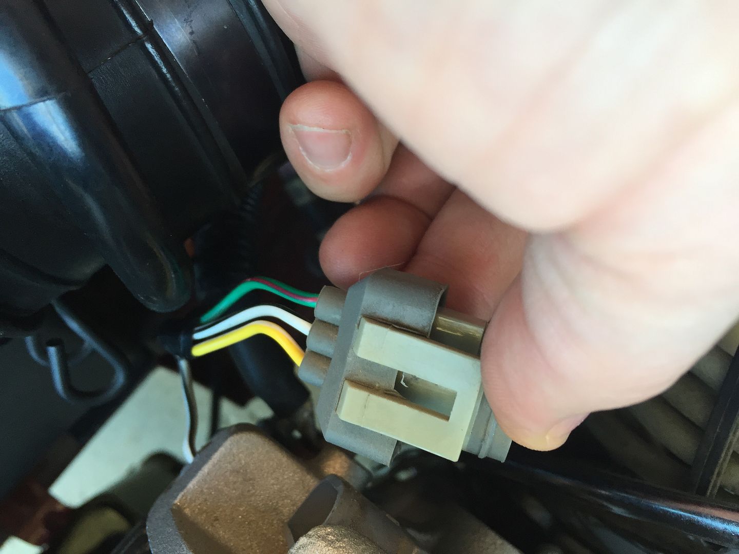
    You have this plug, right?


    Grn/red: I
    Yel/wht: A
    Wht/blk: S

    And your wht/blk terminates to the back of the alt. here.
    Last edited by danco86; 09-15-2016 at 01:04 AM.
    Dan

    http://vb.foureyedpride.com/showthre...ng-GT-restomod


    1986 Mustang GT Cobra
    Lotsa stuff, lotsa work. Check my thread above.

    Daily drivers
    2002 F-350 7.3 Powerstroke crew 4X4
    2012 F-150 Ecoboost Screw FX4

  19. #44
    FEP Senior Member danco86's Avatar
    Join Date
    Feb 2012
    Location
    British Columbia, Canada
    Posts
    731

    Default

    With the Key OFF, grab your meter & put it on the 20 VDC setting. Put the black lead to the -ve battery terminal and leave it there.


    Now put your red meter lead to the +ve lug on the alternator. You should see battery voltage ~12V


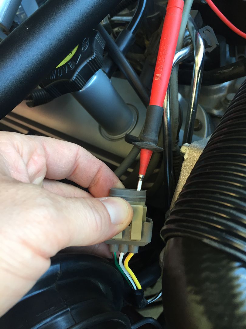
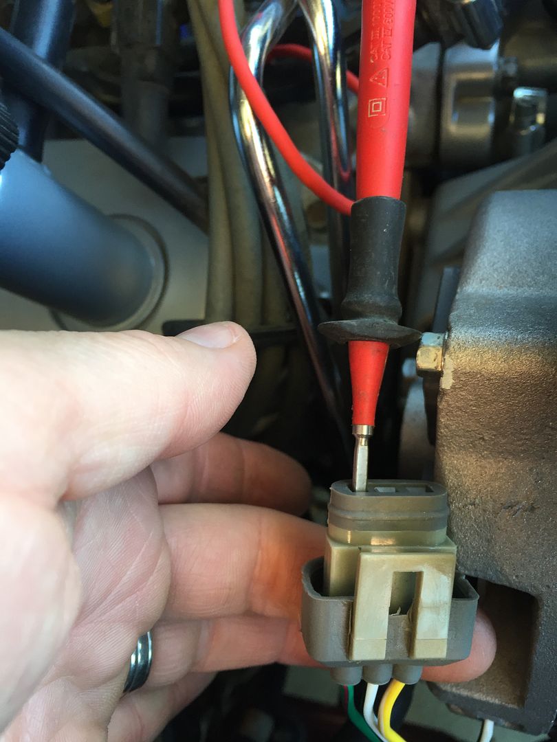
    Now, remove the plug from the alternator. And stick your red meter lead in the plug where the yel/wht wire is. ( see pic) You have to really push the tip in to contact and get a reading. You again, should see battery voltage ~12V.


    Now, go turn the key to 'on' (DO NOT start the engine) just leave the key on.
    Put you red meter lead into the plug where the grn/red wire is (see pic). It should now have ~12V on it. Turn the key off. It should now have 0V on it.

    Last edited by danco86; 09-15-2016 at 12:51 AM.
    Dan

    http://vb.foureyedpride.com/showthre...ng-GT-restomod


    1986 Mustang GT Cobra
    Lotsa stuff, lotsa work. Check my thread above.

    Daily drivers
    2002 F-350 7.3 Powerstroke crew 4X4
    2012 F-150 Ecoboost Screw FX4

  20. #45
    FEP Senior Member danco86's Avatar
    Join Date
    Feb 2012
    Location
    British Columbia, Canada
    Posts
    731

    Default

    I see in your pics that you have the grn/red and yel/wht wires of the plug spliced to the original wires, by doing these checks, we are making sure those wires are good. The yel/wht wire should be hot at all times as it sends the circuit voltage to the regulator. The grn/red wire should only have voltage on it when the key is turned on. This tells the regulator to switch on to excite the field of the alternator.
    Let me know what your results are.
    Last edited by danco86; 09-15-2016 at 01:02 AM.
    Dan

    http://vb.foureyedpride.com/showthre...ng-GT-restomod


    1986 Mustang GT Cobra
    Lotsa stuff, lotsa work. Check my thread above.

    Daily drivers
    2002 F-350 7.3 Powerstroke crew 4X4
    2012 F-150 Ecoboost Screw FX4

  21. #46

    Default

    Quote Originally Posted by danco86 View Post
    With the Key OFF, grab your meter & put it on the 20 VDC setting. Put the black lead to the -ve battery terminal and leave it there.


    Now put your red meter lead to the +ve lug on the alternator. You should see battery voltage ~12V


    Now, remove the plug from the alternator. And stick your red meter lead in the plug where the yel/wht wire is. ( see pic) You have to really push the tip in to contact and get a reading. You again, should see battery voltage ~12V.


    Now, go turn the key to 'on' (DO NOT start the engine) just leave the key on.
    Put you red meter lead into the plug where the grn/red wire is (see pic). It should now have ~12V on it. Turn the key off. It should now have 0V on it.


    Sent from my iPhone using Tapatalk

  22. #47
    FEP Senior Member danco86's Avatar
    Join Date
    Feb 2012
    Location
    British Columbia, Canada
    Posts
    731

    Default

    Quote Originally Posted by congerz83 View Post
    This is negative to the voltage regulator in alternator while the car is running


    Sent from my iPhone using Tapatalk
    Did you take this reading from the back of the alt where the wht/blk wire plugs in?
    Dan

    http://vb.foureyedpride.com/showthre...ng-GT-restomod


    1986 Mustang GT Cobra
    Lotsa stuff, lotsa work. Check my thread above.

    Daily drivers
    2002 F-350 7.3 Powerstroke crew 4X4
    2012 F-150 Ecoboost Screw FX4

  23. #48

    Default

    Quote Originally Posted by danco86 View Post
    Did you take this reading from the back of the alt where the wht/blk wire plugs in?
    Yes. That is correct. Not the plug, but where it plugs in


    Sent from my iPhone using Tapatalk

  24. #49
    FEP Senior Member danco86's Avatar
    Join Date
    Feb 2012
    Location
    British Columbia, Canada
    Posts
    731

    Default

    Your all your wiring appears to check out so far.
    Continuity from the +ve stud of the alt to the battery.
    Voltage on your yellow/white wire.
    Voltage on your grn/red when ignition on.
    The voltage reading coming from where the wht/blk wire plugs in (stator wire) is a little low, mine is about 7.5V. That is just a measurement off of one of the windings of the stator, which is why it is not 12V.

    If you hadn't tried 2 alternators already, I'd say that's what the issue was.
    Is it charging at all, or just low?
    Have you disconnected the battery, negative lead first, while the car is running, and measured the output voltage on the alternator +ve stud to see what it is putting out?
    Dan

    http://vb.foureyedpride.com/showthre...ng-GT-restomod


    1986 Mustang GT Cobra
    Lotsa stuff, lotsa work. Check my thread above.

    Daily drivers
    2002 F-350 7.3 Powerstroke crew 4X4
    2012 F-150 Ecoboost Screw FX4

  25. #50

    Default

    Quote Originally Posted by danco86 View Post
    Your all your wiring appears to check out so far.
    Continuity from the +ve stud of the alt to the battery.
    Voltage on your yellow/white wire.
    Voltage on your grn/red when ignition on.
    The voltage reading coming from where the wht/blk wire plugs in (stator wire) is a little low, mine is about 7.5V. That is just a measurement off of one of the windings of the stator, which is why it is not 12V.

    If you hadn't tried 2 alternators already, I'd say that's what the issue was.
    Is it charging at all, or just low?
    Have you disconnected the battery, negative lead first, while the car is running, and measured the output voltage on the alternator +ve stud to see what it is putting out?
    I'll check that this afternoon


    Sent from my iPhone using Tapatalk

Page 2 of 3 FirstFirst 123 LastLast

Posting Permissions

  • You may not post new threads
  • You may not post replies
  • You may not post attachments
  • You may not edit your posts
  •