


According to my research, the common VR electronic speed sensor used on some speed density, all criuse control , and all Fox Tbird/Cougar XR7's, VII's and LSC's.
The cruise control runs off a variable Reluctor disk on the standard cable speedo drive
http://vb.foureyedpride.com/showthre...roubleshooting
[QUOTE=JACook;1612943
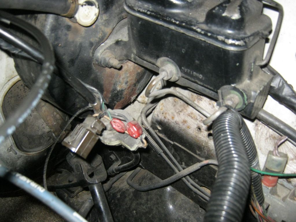
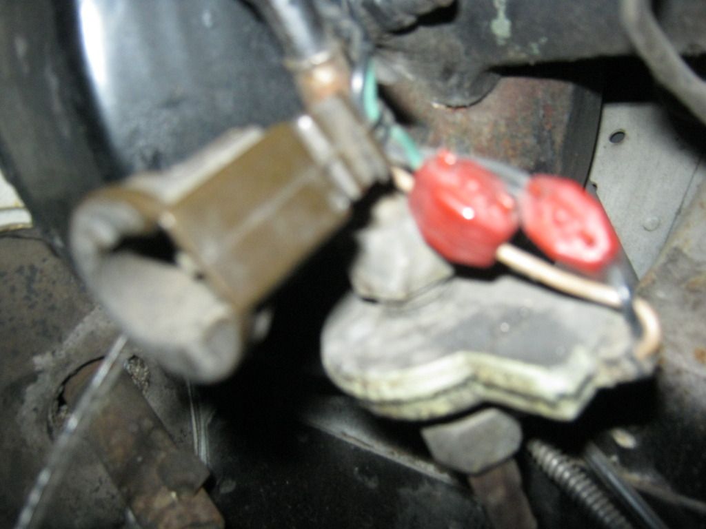
To check the electrical continuity of the VSS circuit, you should see 200Ω-300Ω between the dark
green/white wire and ground. (This wire should also show a voltage signal when the car is moving,
that is proportional to speed.)
[/QUOTE]
From the F truck forums and Variable Relector info on the net.
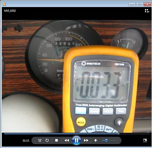
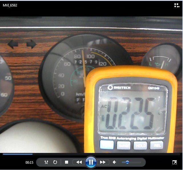
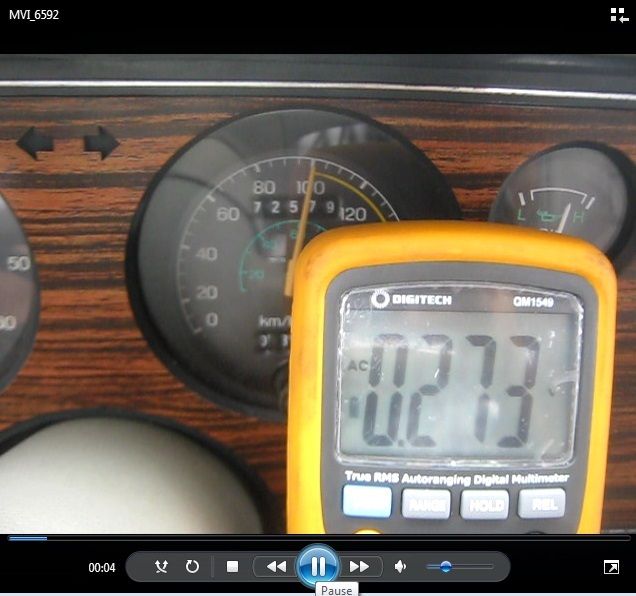
"On an AC, permanent magnet sensor, both AC voltage and frequency increase with the speed of the trigger wheel. The AC voltage should range from
0 volts at 0 MPH to 3.5 volts at 30 MPH. Frequency should increase from 0 Hz at 0 MPH to about 125 Hz at 55 MPH"
The EECIV spec XF-AU Aussie Falcns had 102Hz = 37.28 mph (60km/h)
I've just ruined my second Bernstein NPN sensor, and need something that produces not more than 5 volts positive, and a square wave form for my data logger.
I'm thinking of a straight wire hookup to my VR sensor.


 Reply With Quote
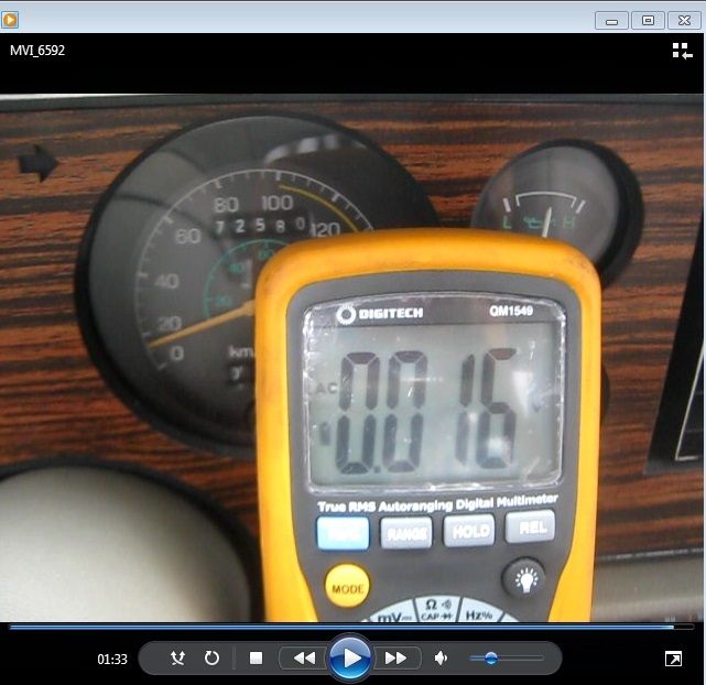


Connect With Us