


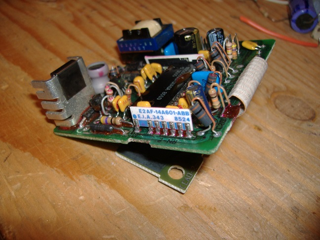
The good news is that I figured out, definitively, what the problem was. It wasn't the dimmer circuit but that did lead me to the real problem. It was a thick-film resistor network. It's the white thing standing up in the picture below.
There are three resistor dividers on there, one for each power wire. They drop the voltage to a safe level to feed a pin on that big chip in the middle of the board. The dividers for the dimmer and ignition wires were working properly. It was the third divider that feeds the battery voltage to the chip (I assume for brownout detection) that was drifting. I could watch it with a volt meter drop from 2.5 Volts. As soon at it went below 1.6 Volts the screen would turn off. I could get the voltage above 1.6 Volts briefly by blowing on the resistor network. The screen would come back on until the voltage dropped then the screen would go off again. It looked like it had some cold solder joints so I fired up the soldering iron and re-flowed them. Powered on the Tripminder again and the voltage was still drifting. Now here comes the bad news...
While checking the voltage, my probe slipped and bridged the gap between pins 2 & 3 on the resistor network which sent full battery voltage to the chip pin, frying the internal protection diode. It's now permanently pulled down with no way to get it out of brownout mode. GAME OVER

 Reply With Quote
Connect With Us