Close


Results 1 to 2 of 2
  1. #1

    Default 91' N/A 2.3 Electrical problem

    Hello, Im new to the forum and was referred to by a friend with an SVO, well I just bought my 91' yesterday and drove it home and parked it, went to start it again and it went dead, I have suppositions that it is the stripped out negative side post terminal not allowing a good enough connection to the battery. But any other ideas as to what this might be? before I go sinking money in the wrong places.

  2. #2
    FEP Super Member xctasy's Avatar
    Join Date
    Jun 2012
    Location
    Dunedin 9011, New Zealand, South Pacific
    Posts
    3,961

    Default

    Before goin any further, have a competent electrician First check the continuity of the EEC IV central processing unit. The Fo Mo Co EEC was and, based on what was around in 1991, is the best system around for design and support, but there are a few age induced problems that can happen, and no further money should be spent untill the follwing two avenues are investigated first.

    1. Read this...http://www.stangnet.com/mustang-foru...switch.772570/


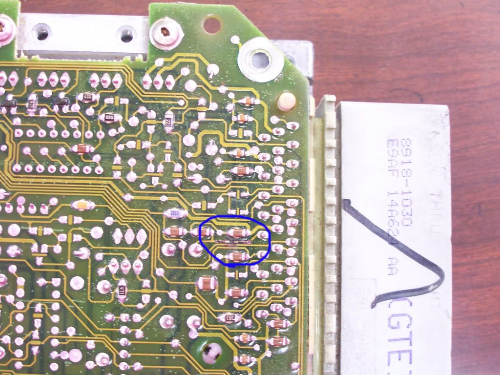
    Not listed on Fords service bulletins, and much more common now in a vibrating 4 cylinder engine in a light unibody car is that as the intel built computer board ages, the capacitors fail to meet continuity, the the EECIV goes into a head spin, and suddenly no one knows if its the earth strap, a flat battery, the EGR valve and lines....or what! A whole raft of faults can be raised, or no faults raised, but the Central processin unit won't work, and the old machine ends up gettin junked because no one can fix or diagnose the problem. Its very common with the electronic injection 2.3.

    2. From http://forums.corral.net/forums/eec-...cher-here.html

    For yours, there's only 3 electrolytic capacitors on the board. They are

    two 47uF, 16V and the one near the top that seldom fails is 10uF, 6.3V.

    Acceptable replacements for the two 47uF, 16V capacitors can be the 47uf, 35v.


    If you're holding the PCB with the connector facing upwards:

    1) Near the middle of the board, closer to the connector. In my experience, this one is typically ok. I'd replace it on principle.

    2) Left edge of the PCB, below the heat sink for the injector drivers.

    3) To the right of the MCU, above the maroon poly cap directly over the J3 port.

    You'll be able to tell pretty easily if they're failing. Look closely at the bottom for any discoloration, and wiggle the cap lightly. If they move without any resistance, there's discoloration on the bottoms, they're swollen on either the top or the bottom, or the PCB looks like it has a "shadow" under the cap, then they're bad and need to be replaced.

Posting Permissions

  • You may not post new threads
  • You may not post replies
  • You may not post attachments
  • You may not edit your posts
  •