
Keep up the good work


Keep up the good work
~Bryan
1985 Mustang GT w/ T-Tops, Original Paint, 160,XXX miles
Mods: 600cfm Carb, Underdrive Pulleys, Subframe Connectors, 4pt G-Load Brace, MM Strut Tower brace, 8.8 rear w/ 3.55 gears & LCA's
Pics from production of "The Saleen Book"
http://www.facebook.com/album.php?ai...&id=1027847075
http://mustangworld.com/ourpics/News/select1271.htm


Awesome project!
1998 SVT Contour Daily Driver- K1 Racing Wheels CAI
1985 Mustang GT T-top Black
Freshened/Blueprinted 302-Heavily Worked GT40 Heads SS valves and Heavy Duty springs-1.6r Crane Cams RR-Custom Grind Comp Cam-Wieand Intake-Edelbrock Carb-MSD-King Cobra Clutch-World Class T5-Cobra 4whl Disc-31spl 4:10 rear-Longtubes-Strange 10Ways-Mac Exhaust with 3" Rolled tips-
1984 RS Turbo Capri 100% Show car
1982 Mustang GT

Its coming along real nice it will be an outstanding car when your done


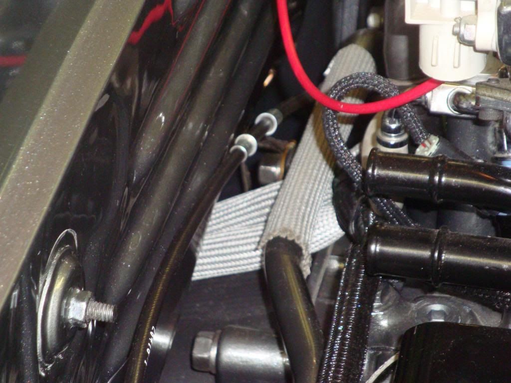
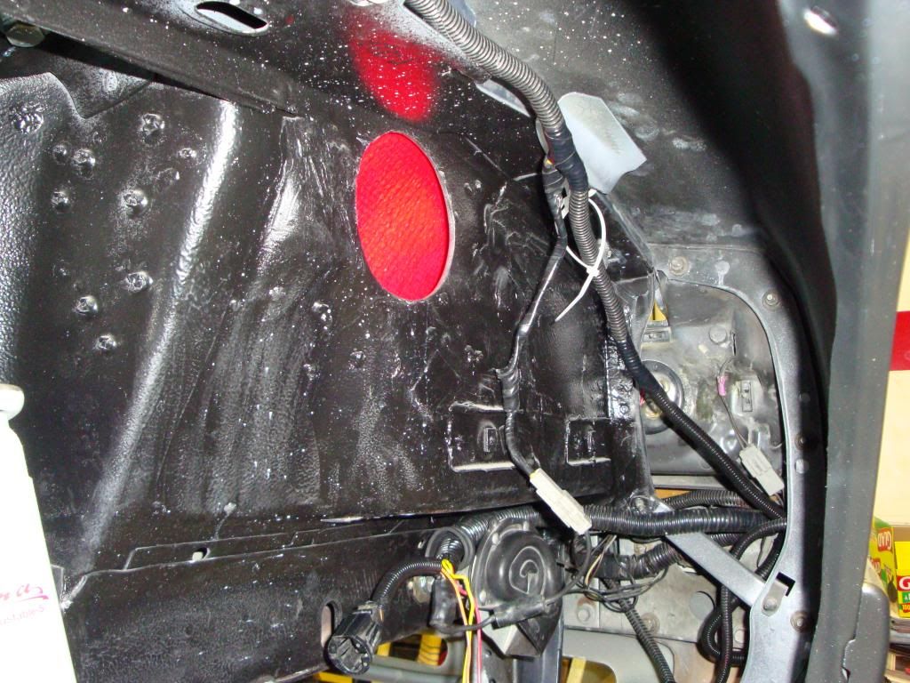
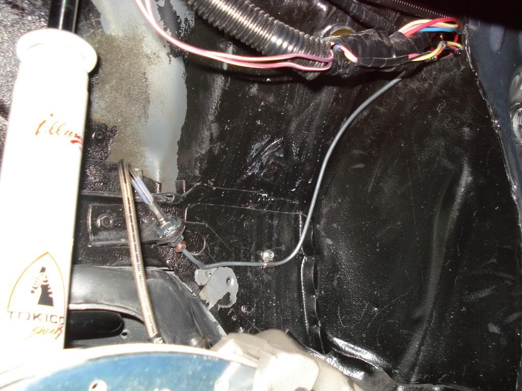
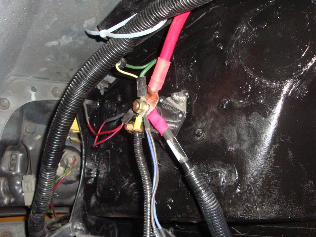
Here is a picture of some of the wiring loosely hung in the drivers side fender.
You can see the starter solenoid mounted on two studs that were welded in during the body work. The headlight wiring goes forward and is hidden in the nose under the grill opening.
With the hole in the firewall, I was able to get both the wiring and the brake lines (still to be done) through the opening. Also, I used bulkhead connectors for the battery cables in the drivers side fender well.
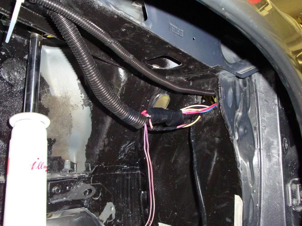
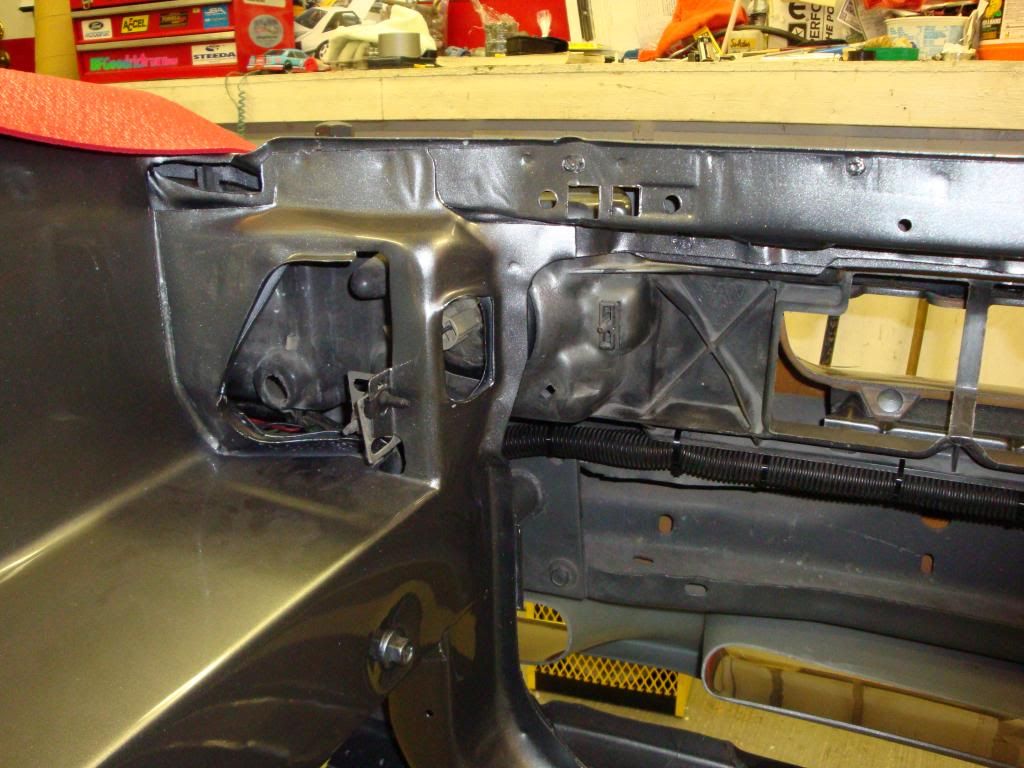
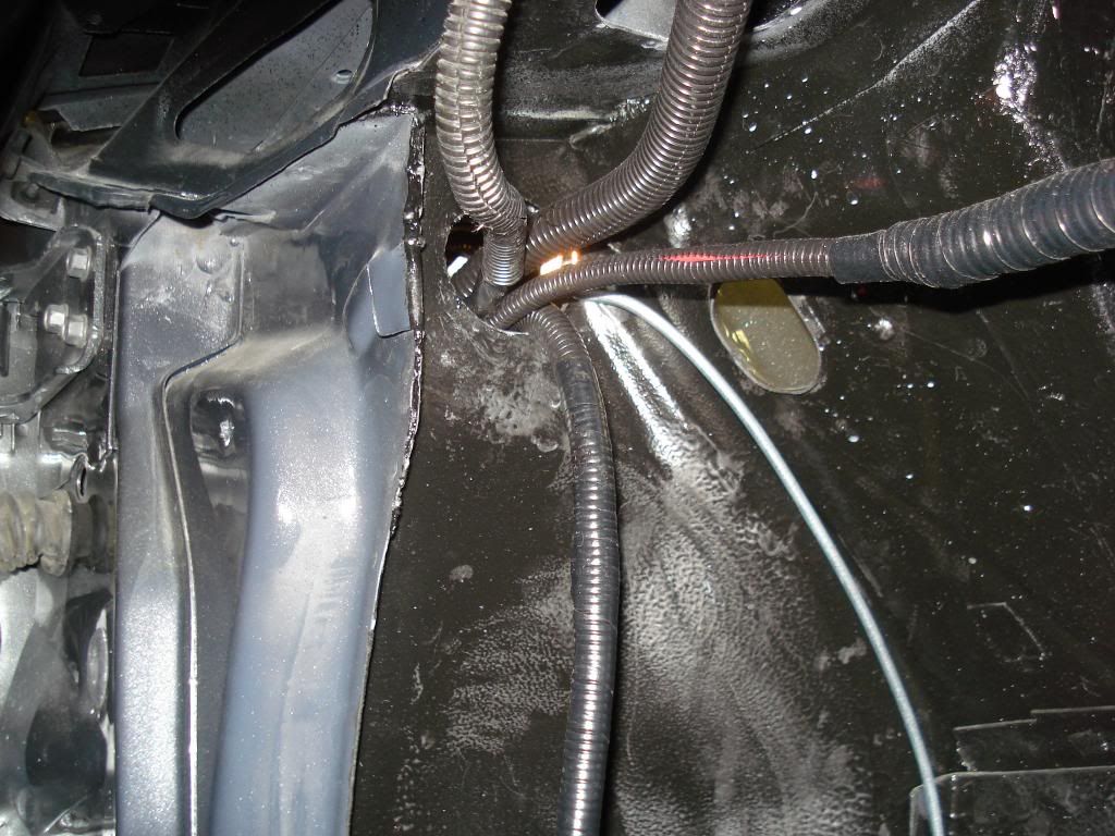
Here is the hole on the passenger side. Wiring and the brake line fit through this opening. The hole behind the shock tower was retained so that vacuum lines could go into the engine compartment.
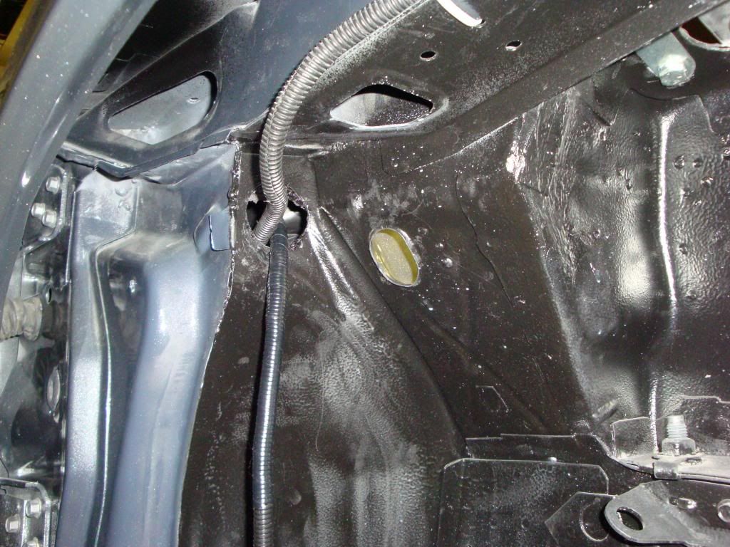
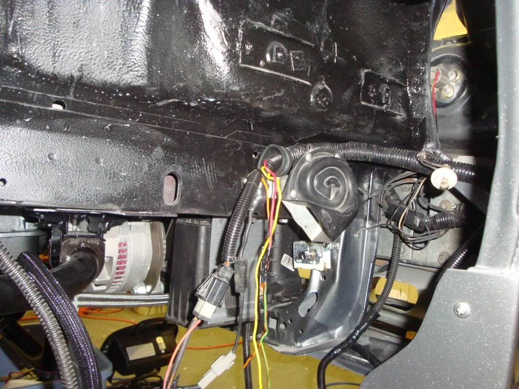
This is the front of the passenger side. Wiring, including alternator wires run through here. The wiring for the mass air meter will be in here as well. The mass air meter will be located in between the tire and the headlight.
This picture shows the wiring hidden under the grill opening in the front of the car.
At this point, I have most of the body wiring in the car. I found that to get the new third brake light to work properly, i had to run a wire (yellow wire on floor) from the 3rd brake light right up to the switch on the brake pedal.
So, I got the engine in the car. I operated the hoist while my daughter watched for clearance as the engine was slowly lowered in. Then, I put the transmission on a hydraulic jack, rolled it under the car and my wife raised it up while I lined it up with the engine. It was nice once everything was bolted up and nothing got scratched. Good team work.
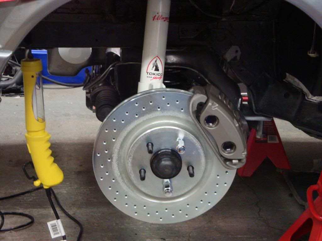
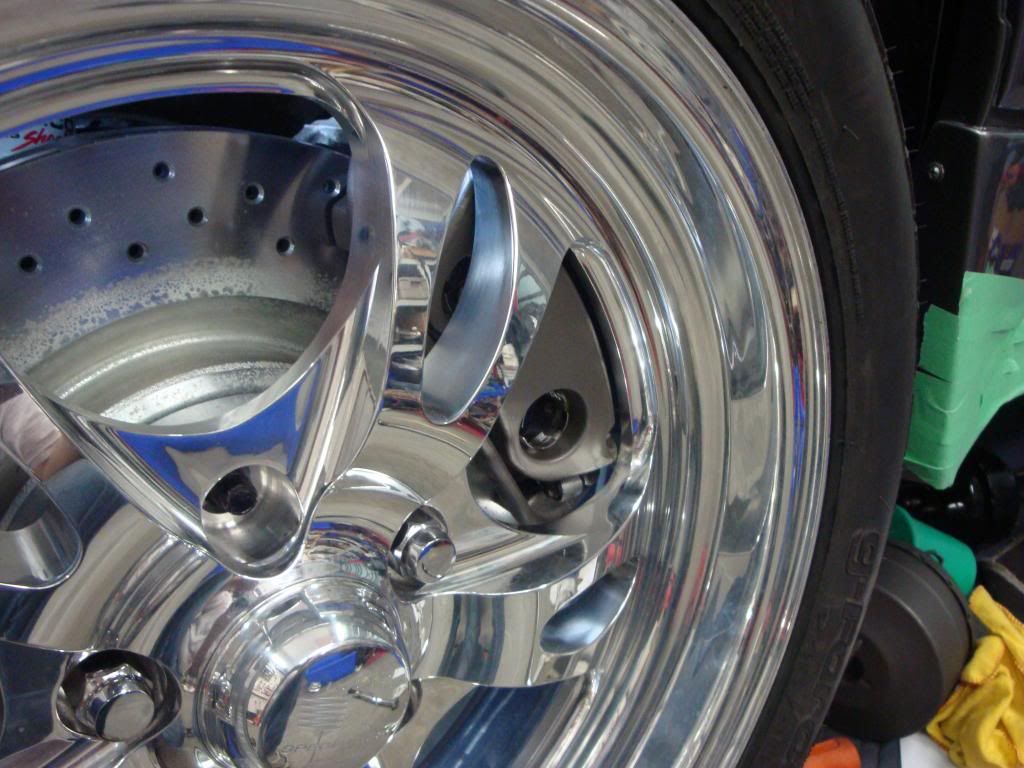
So, onto the brakes. I already had the 92 front brakes with the 11 rotors. I wanted to go to the 13 Mach 1 brakes. These are the same as the Cobra brakes but the callipers dont have any words on them. I had both the 1995 and 1996 spindles but I choose the 95 ones as I wanted to keep the wheels tucked in close to the body. Also, with 17 wheels, I did not want clearance issues with the fender. So now Ill mention that I had already measured and ordered custom wheels that were made to my measurements. When they arrived, I took a hub and a rotor and checked for clearance, everything was good. I was happy.
Then I started putting the front brakes together, doing the drivers side first. They looked great, so I tried the wheel. The calliper touched the wheel and the wheel wouldnt turn (good time for a break). So, I talked to Billet Specialties to get a 1/8 spacer. Then, I called Maximum Motorsports and explained my problem. The answer came in longer wheel studs. But, fyi they wouldnt sell me the Moroso studs, only the stronger ARP studs. Given that I didnt want my front wheel to come off, I was happy to go with their suggestion. (You need 6 to 7 treads inside the nut to hold the wheel on). So, I took the calliper, rotor and hub off and had to get the studs pressed out and the new studs pressed in. Then once reassembled with the wheel on, I measured the length of the studs. Then, I had to remove the wheel, screw a nut on each stud and cut them to the proper length. Then, unscrewing the nuts helped with the threads on the end of the studs.
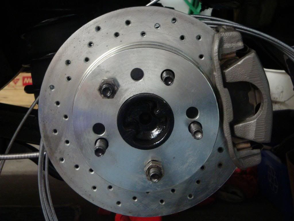
My rear brakes had originally been converted to discs using the M2300-C kit. These were 10, 4 bolt. This was the Motorsport kit that gave you rear discs the same as the 88 and 89 Thunderbird Turbo coupe. So, to update and convert to 5 lug on the rear, I got the Motorsport 5 lug axles and swapped them in. Then, I bought new rear rotors and had them re-drilled to 5 lug. This way, I was able to reuse all the other existing parts.
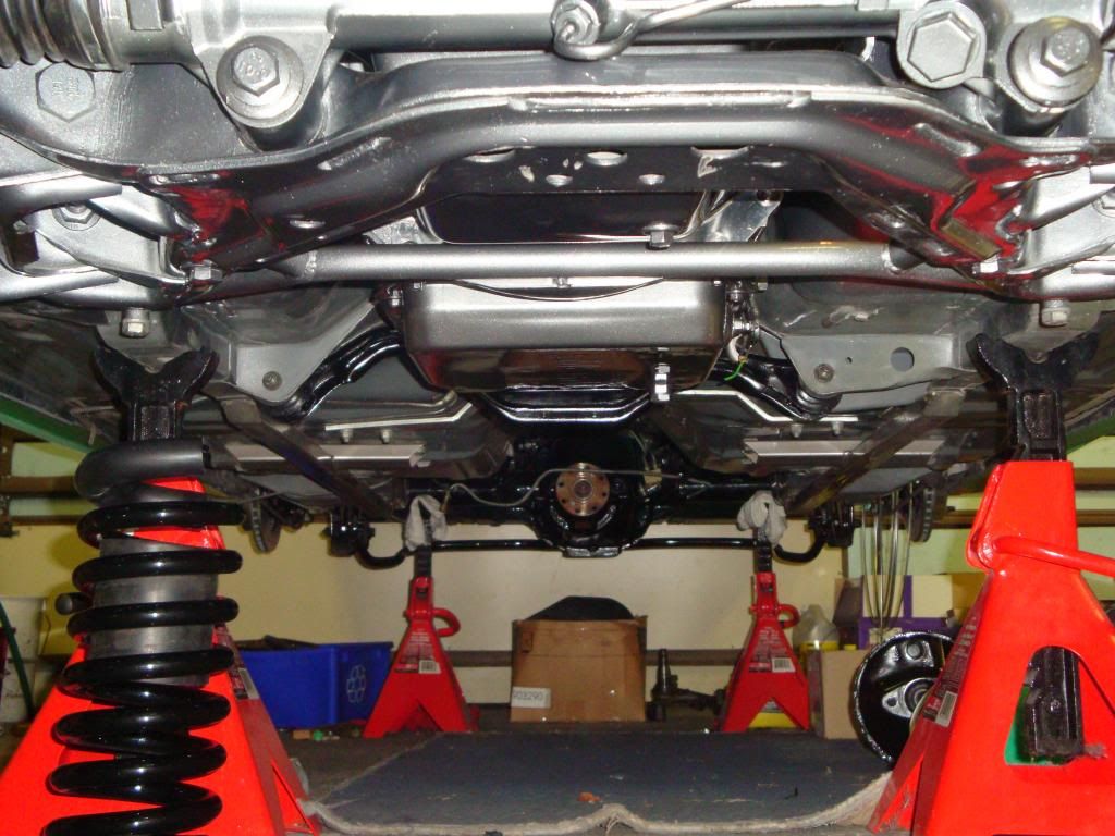
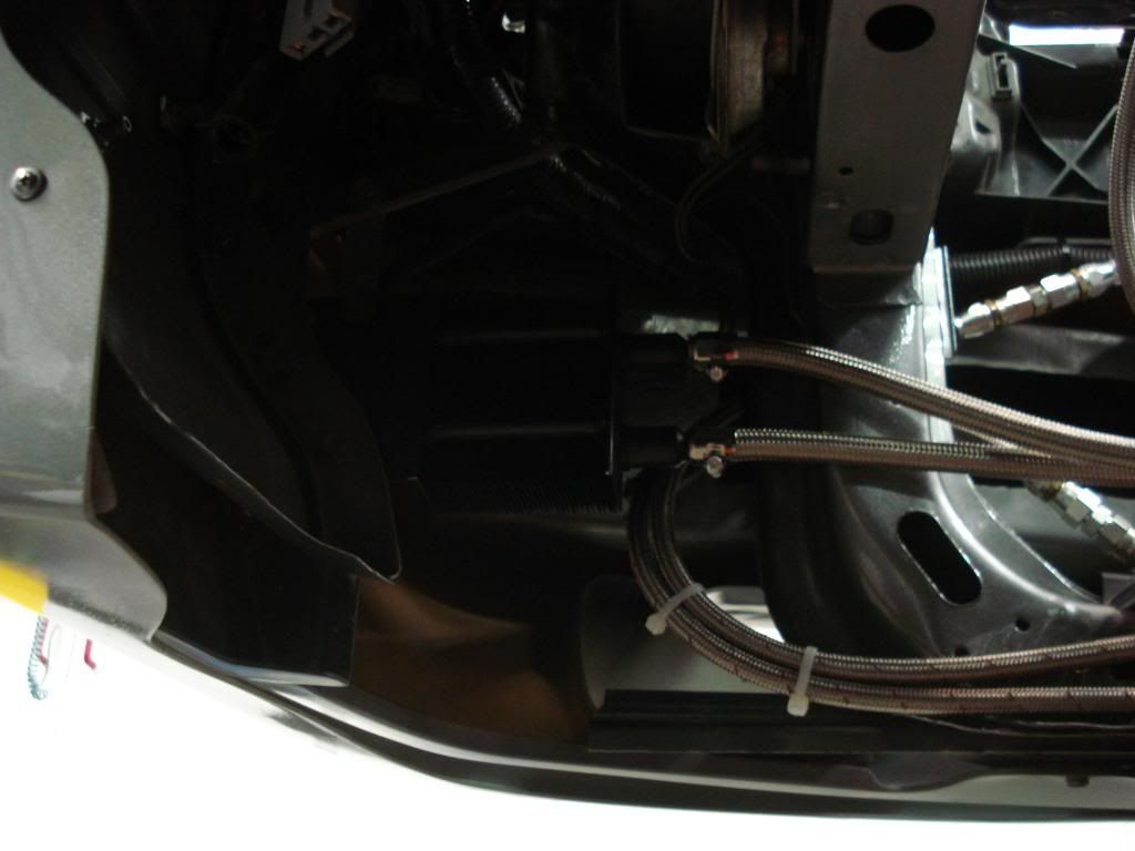
Here is a picture looking under the car after the rear brakes were on. The brake lines still have to be done.
More later...
I have to say something: I ABSOLUTELY LOVE the color of your car, its not an original color is it? Its awesome! neither light nor dark, kind of the color of mercury or lead...
This car is going to look amazing when finished!
Sorry for the delay getting back. Computers are great when they work and wonderful when they don't.
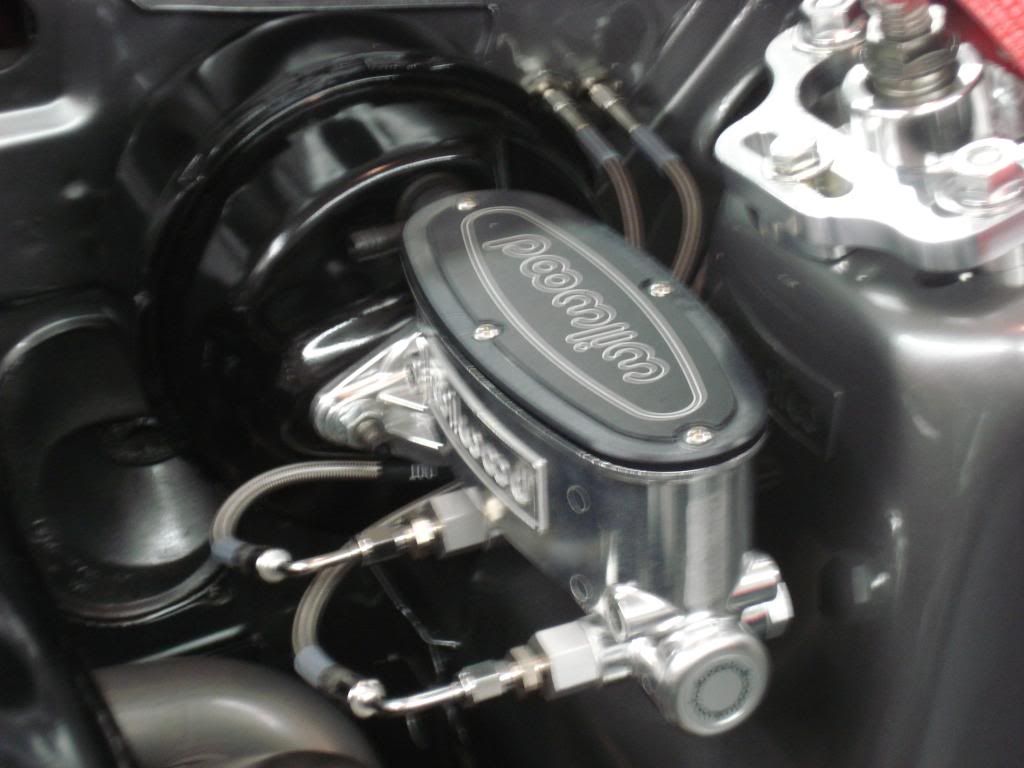
Here is a picture of the Wilwood tandem master cylinder (polished with a 1.00 bore) that I am using. The master cylinder allows for the lines to attach to either side of the master giving you lots of flexibility. For the side you don't attach lines to, Wilwood provides plugs to go in the holes. The part number for the one I used is # 260-8555-P.
I am also using the original brake booster - I tried to get the cobra brake booster (I bought a brand new one) to fit and I would have had to "massage" the shock tower even after elongating the mounting holes but, since the car was already painted I chose not to. So, if youre changing the booster, my suggestion, do it before you paint your car.
If you choose to change your brake booster, I would suggest the one for the '93 cobra (they are available). The later model boosters (1996-9before hydroboost, have a different shaped arm that goes through the firewall and connects to the pedal assembly...these may bind...not recommended. But, I have found that even with using the original booster, my breaks work great. I used Russell braided brake lines running from the master to the firewall where I put in bulkhead fittings and ran the lines inside the car. I eliminated the distribution block as I also have a proportioning valve inside the car.
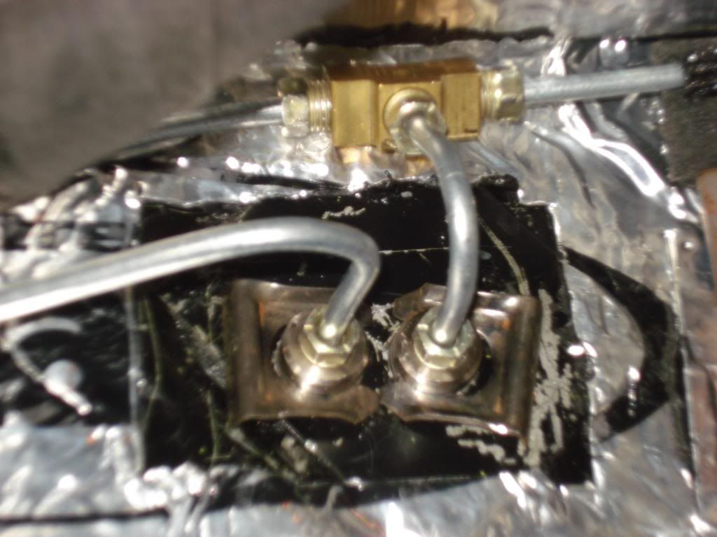
Here are the brake lines coming through the firewall from the master cylinder. The line on the left goes to the proportioning valve and then to the rear brakes. The line on the right splits and goes to the front brakes.
Brake line running across firewall and going to passenger side front wheel. You also see some of the wiring running through firewall to right front corner.
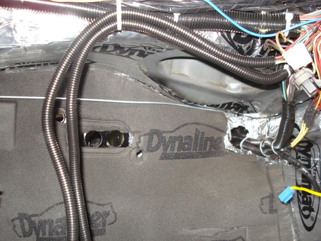
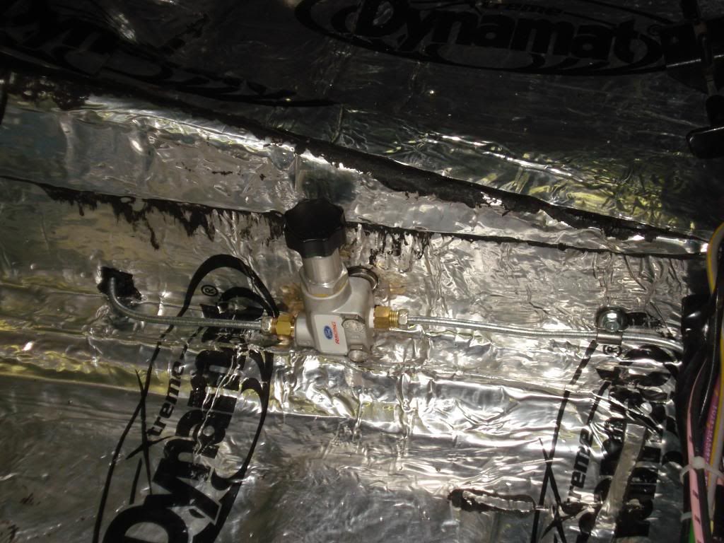
The brake line runs inside the car along the inside of the rocker panel, to the proportioning valve in front of the rear seat and then exits underneath to the rear brakes.
Drivers side brake line running to the front wheel.
Passenger side brake line.
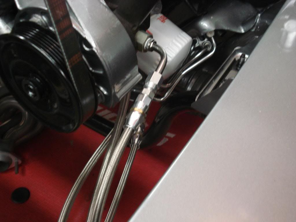
I installed a heavy duty transmission cooler in front of the rad. I went with braided lines and proper fittings to ensure no leaks. In the past, I had a line blow off and at 200psi, you loose your fluid in a big hurry and create an instant lake. The other braided lines are for the power steering and they lead to a cooler (from a 93 cobra) in the fender well.
Power steering hoses
Here is a picture of the power steering cooler mounted in the fender well.
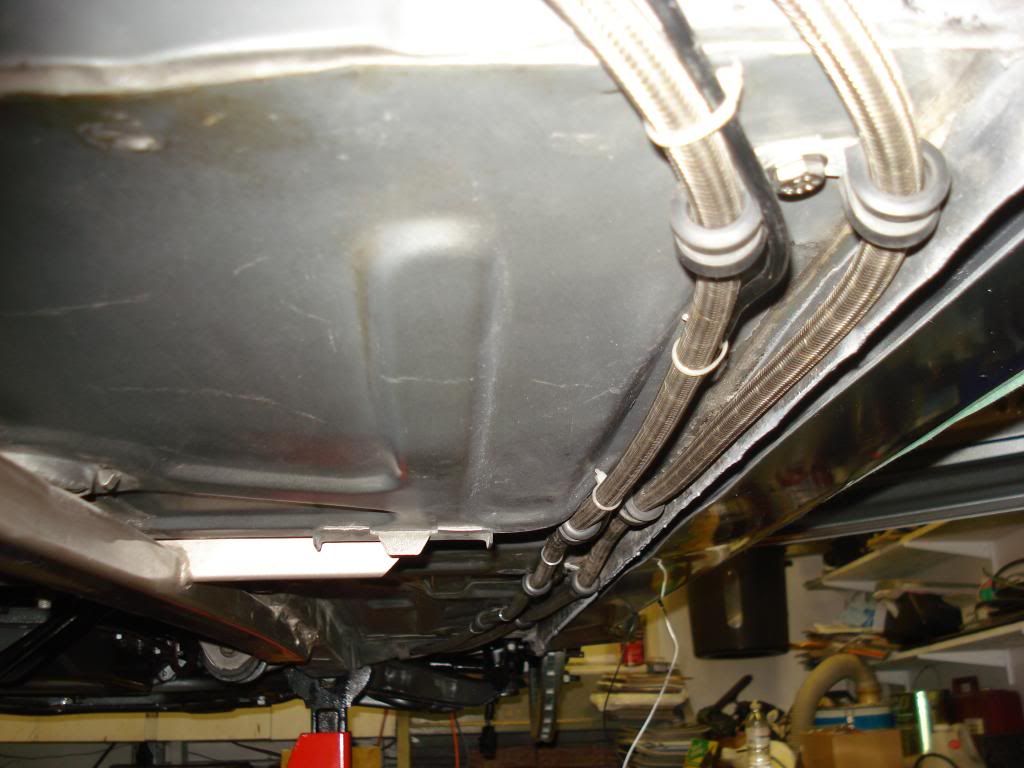
Fuel lines running from the rear, up the passenger side to the front of the car.
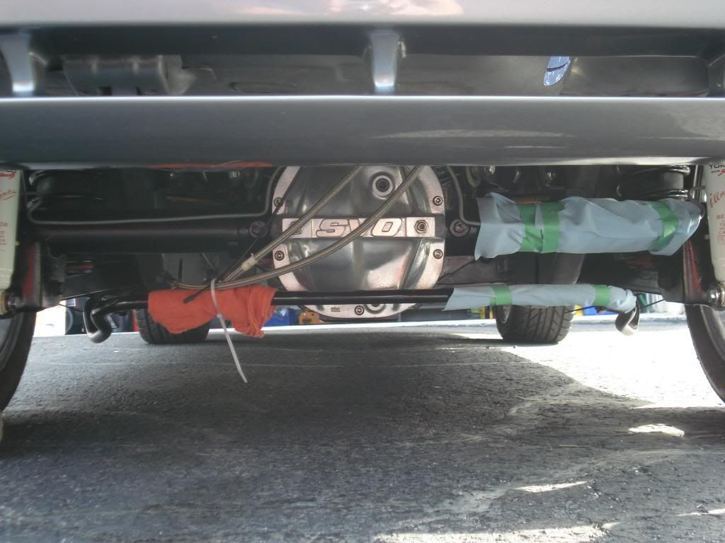
Here is the 8.8 rear that was installed after I blew the 7.5 rear apart. This one has the stud kit and the girdle. The SVO girdle was coated (the same coating that is applied to headers) for a clean, maintenance free appearance. Also, the rear sway bar is from a 92 5.0L car as it is larger in diameter.
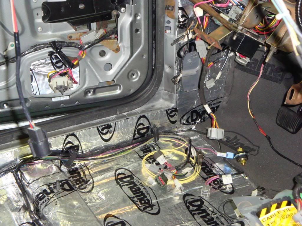
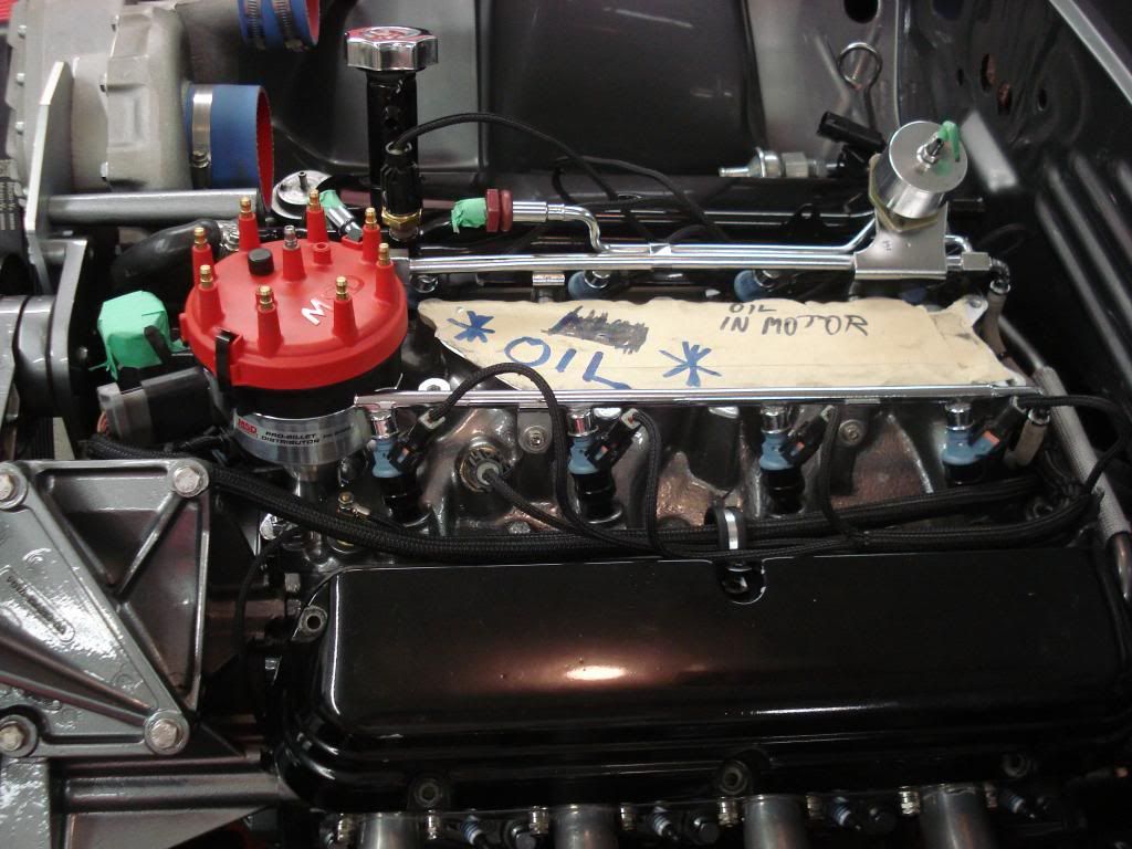
This picture shows the wire covering I used from Painless Wiring. I also made sure that I knew if the engine had oil in it as I got closer to being able to start it up. At different times I was priming the motor to keep the oil circulating.
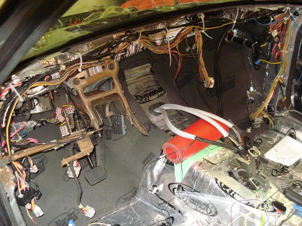
Here is a picture of where I brought the wiring for the 10 pin connectors into the car. They are covered in thermal casing for a heat shield. They will connect up under the dash.
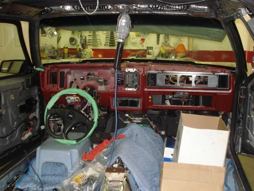
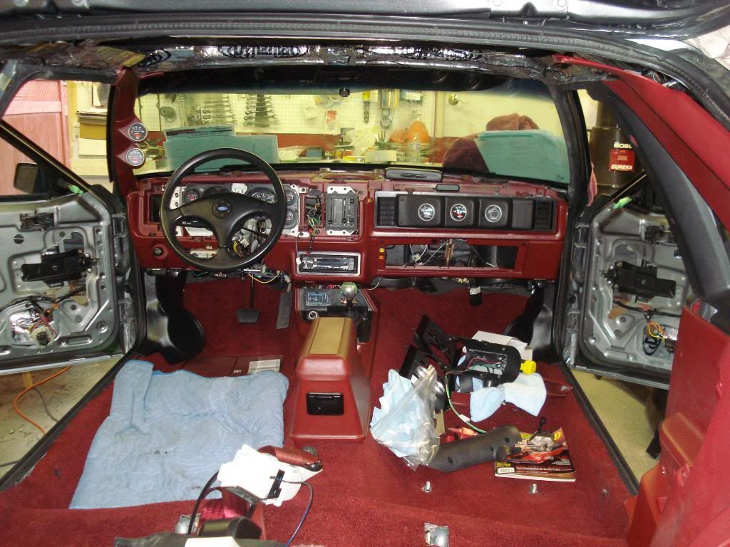
So, I got the dashboard in the car and started hooking up all the connectors around the steering column and the 2 ten pin connectors up under the middle of the dash. The face plate on the passenger side of the dash is one I got from another car. The original one only has a vent on the right side by the door because the car didnt come with A/C.
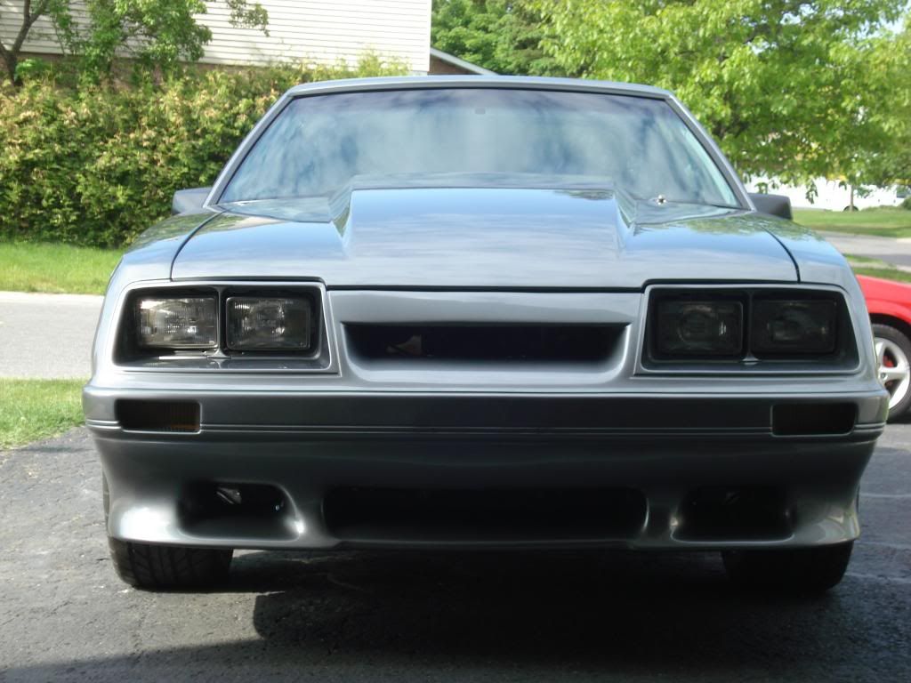
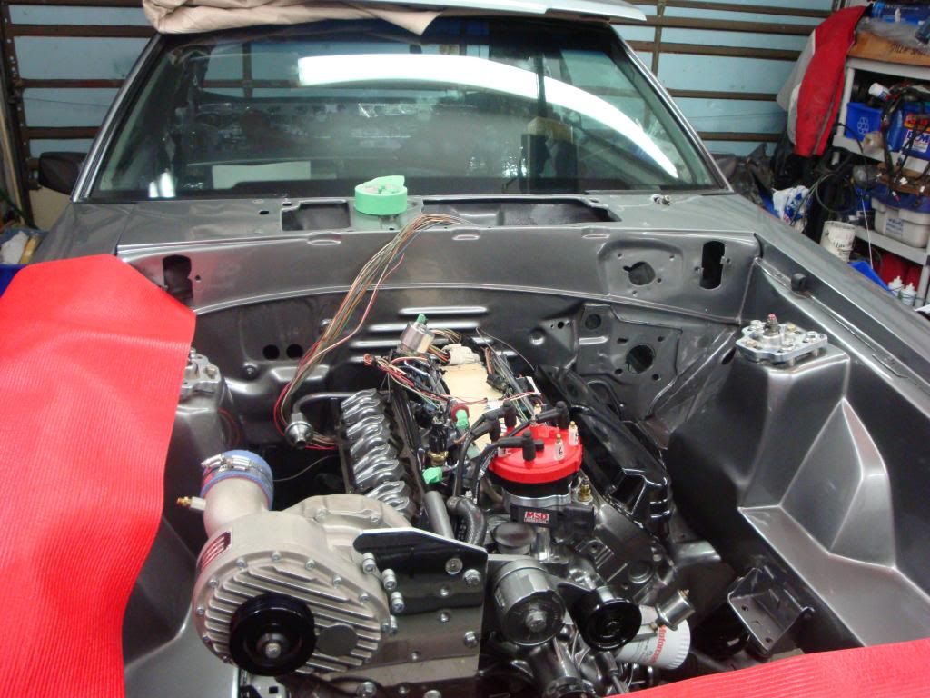
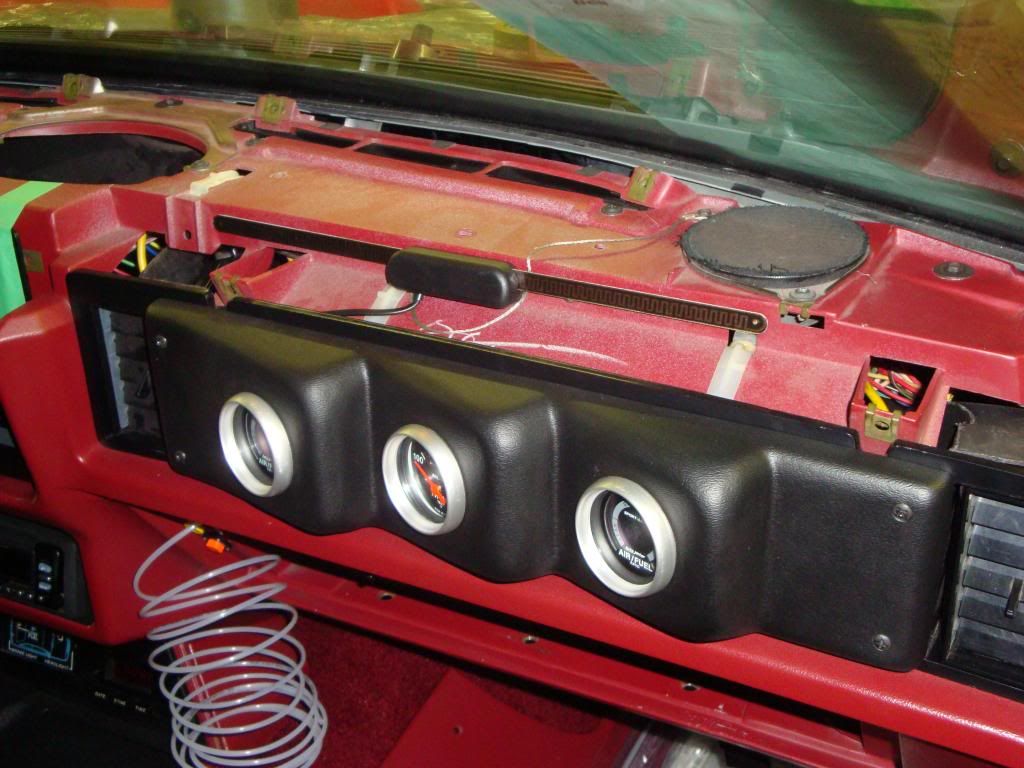
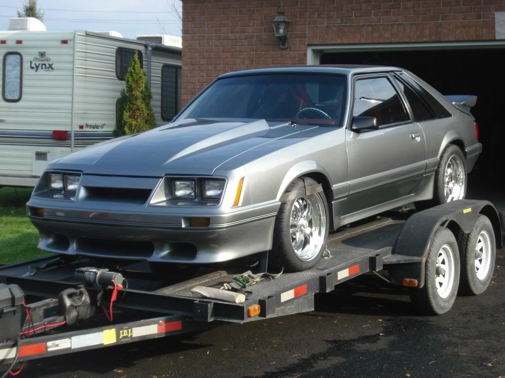
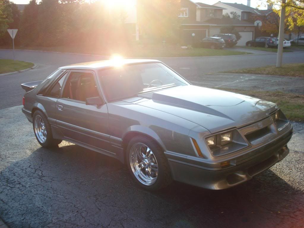
Here is a picture of the front at this point in time.
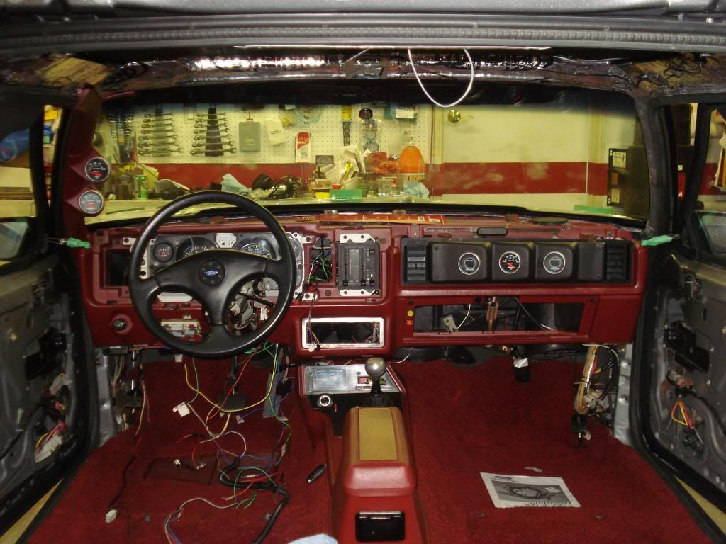
The car is starting to get the interior back. The steering column is back in and connected to a Maximum Motorsports steering shaft. The console and carpeting are in. The gauges on the passenger side are in a Florida 5.0 gauge pod.
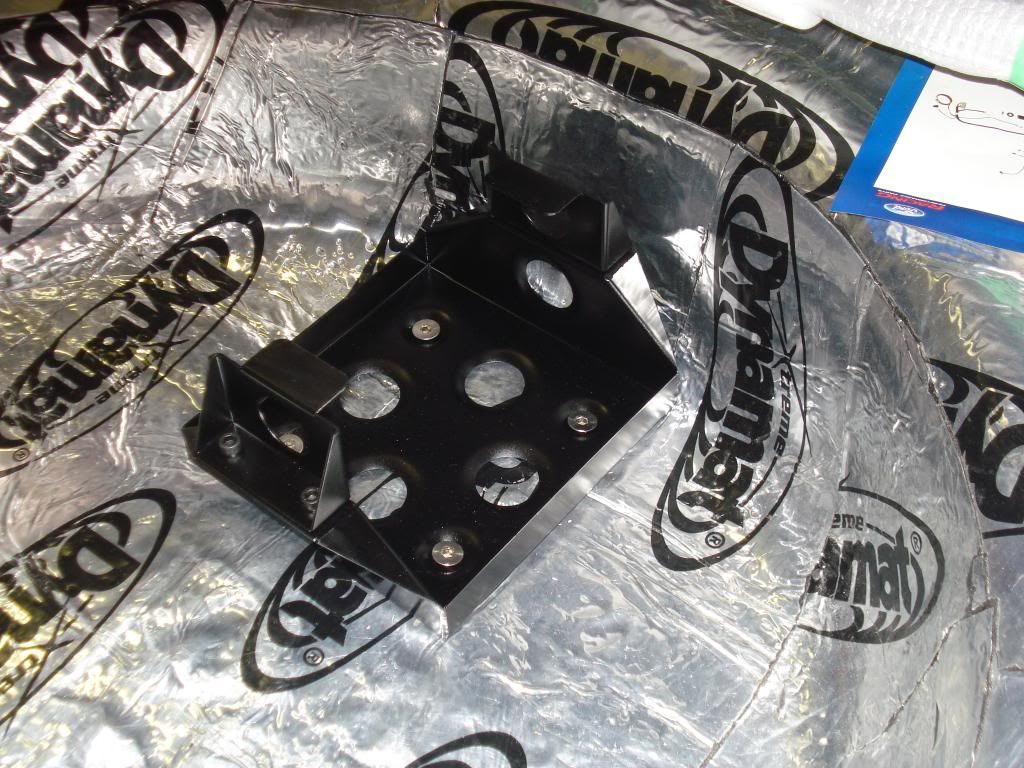
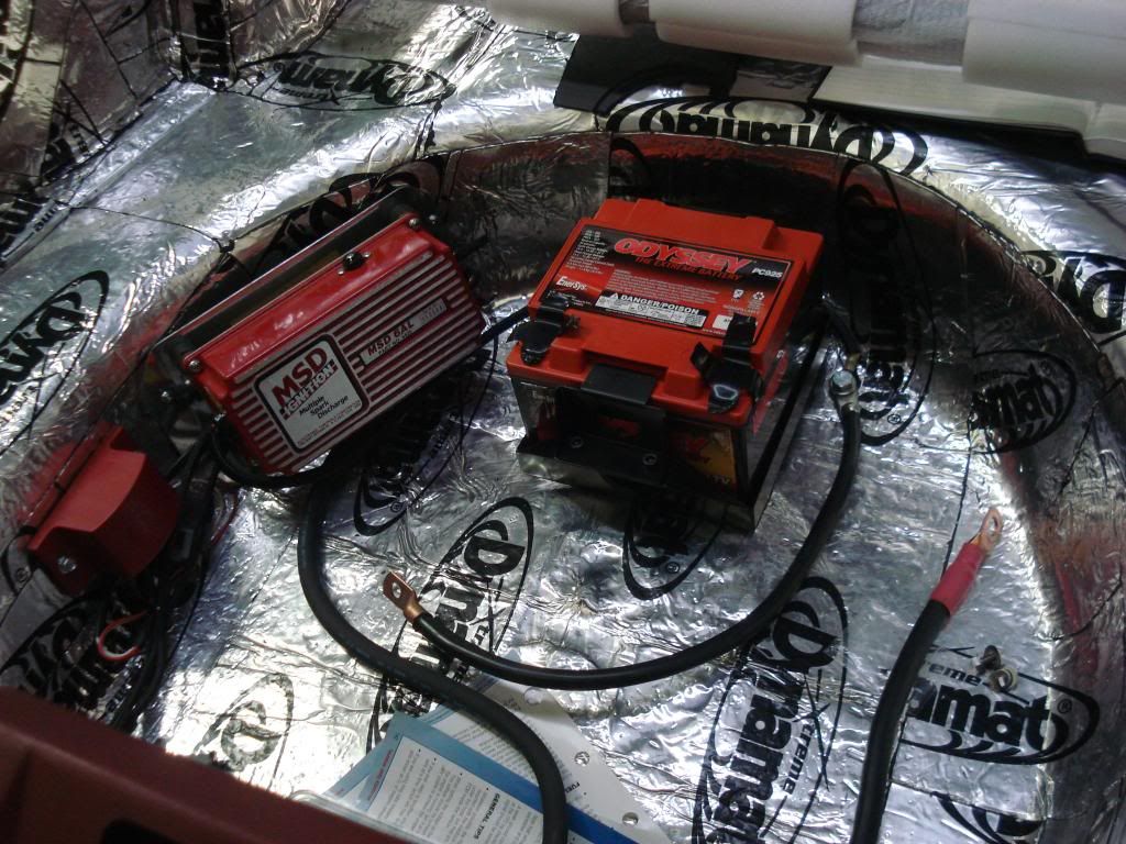
Here is the battery tray that I am using and mounted in the spare tire well. This tray fits the Odyssey PC925 battery.
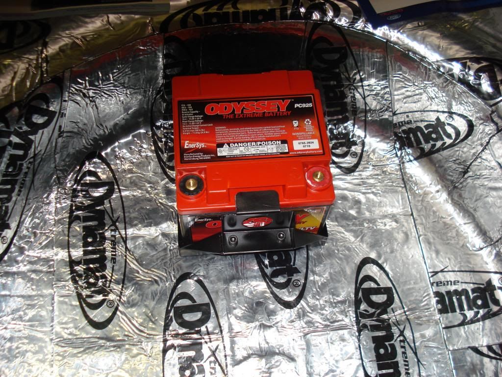
Here is the battery in the tray.
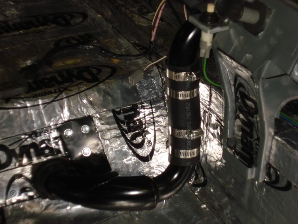
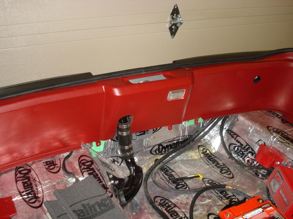
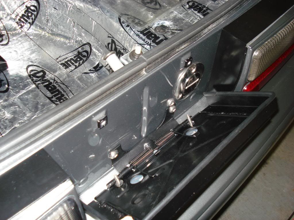
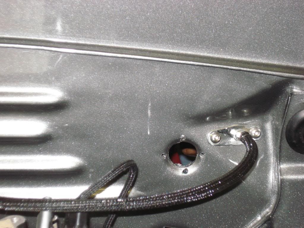
So, some of you asked how I was going to put gas in the car after shaving the filler door. With a hole between the tail lights, I used a Cool Cap and had it welded on to a filler neck that runs down into the spare tire well and connects, using a rubber gas filler hose, to another fabricated piece that goes to the gas tank. I also used a new seal around the gas tank opening. To move the opening on the tank, I first had it pressure washed (very important to eliminate any vapours), then the filler hole was cut out (a square section) and a corresponding square section was cut out on the other side of the hump. The two pieces were swapped, welded and the tank was pressure tested. All other fuel fittings and wire connections remain the same. The rubber gas filler hose (NAPA) allows me to remove it if I ever need to. Then, to hide the gas cap behind the licence plate, I used the hinged licence plate bracket for an early Camaro or Monte Carlo. The bracket was then enlarged and sides were added. After powder coating black, rubber trim was added. Then I altered it so I could lock it shut.
This is how the fuel filler neck turned out. Yes, it is off center because I didnt want to weaken the bracing for the hatchback latch.
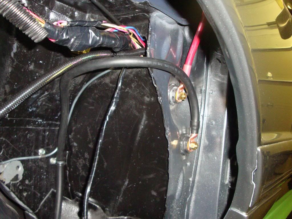
Both the positive and the negative battery cables for the car were made to length from welders cable and are 1/0. They run from the battery in the rear inside the car on the drivers side to the wheel well inside the car where they connect to bulkhead fittings. Once they were finished and before they were connected to the battery, insulated covers were put over both terminals in the car and in the wheel well. In the fender well, the positive cable goes to the starter solenoid. From there, the positive leads to the starter. The starter was updated to a one wire starter like the 92 mustangs. From the bulkhead fitting, the negative goes to the transmission bell housing to act as a ground. There is also a second ground from the engine block to the frame. Back at the battery, there is a third ground in the rear of the car.
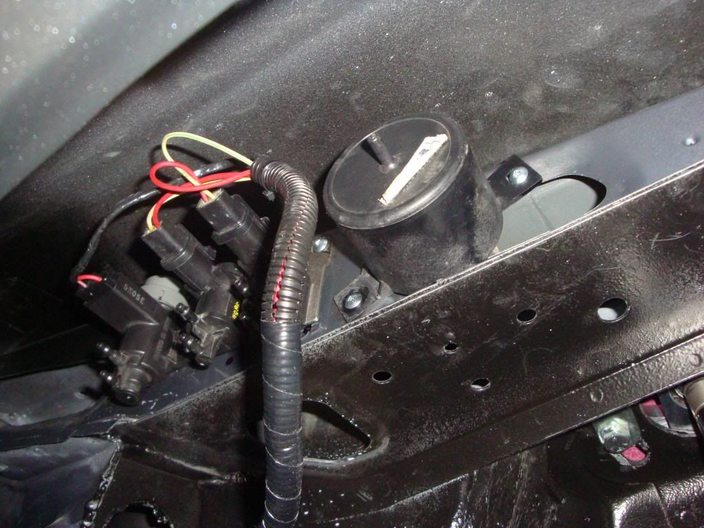
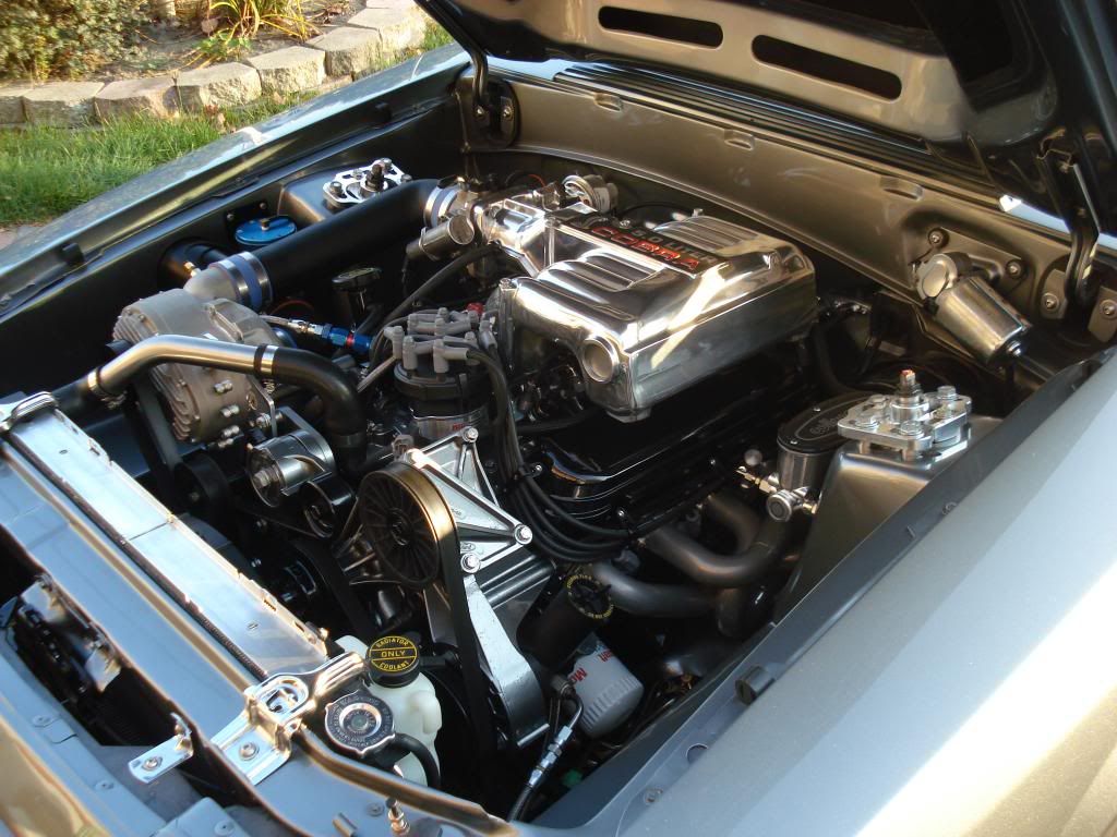
The thermostat control can be seen on the lower rad support. The dial is set to maintain 180 degrees. The fan will run when the car is turned off until it cools down.
The wiring and vacuum lines can bee seen in the passenger side wheel well up on the frame rail.
A hidden antenna from Autoloc is fastened to the dashboard and sits under the dash pad. This was installed as the original antenna was shaved from the top of the fender.
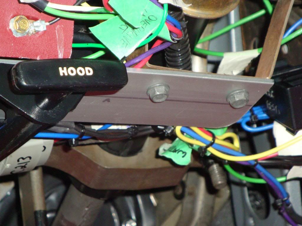
When I moved the hood release cable from the engine compartment into the drivers side fender to hide it, I had to make a bracket to move the release handle a few inches closer to the side. Otherwise, I would have had to lengthen the cable. Also, on the right side of the picture, you can see the diagnostic connection that I moved inside the car.
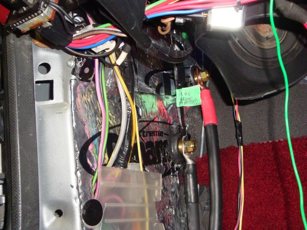
With moving the battery to the rear with an EFI engine, you are supposed to run a wire and still connect the computer ground straight to the battery. I was able to connect the ground at the bulkhead connector.
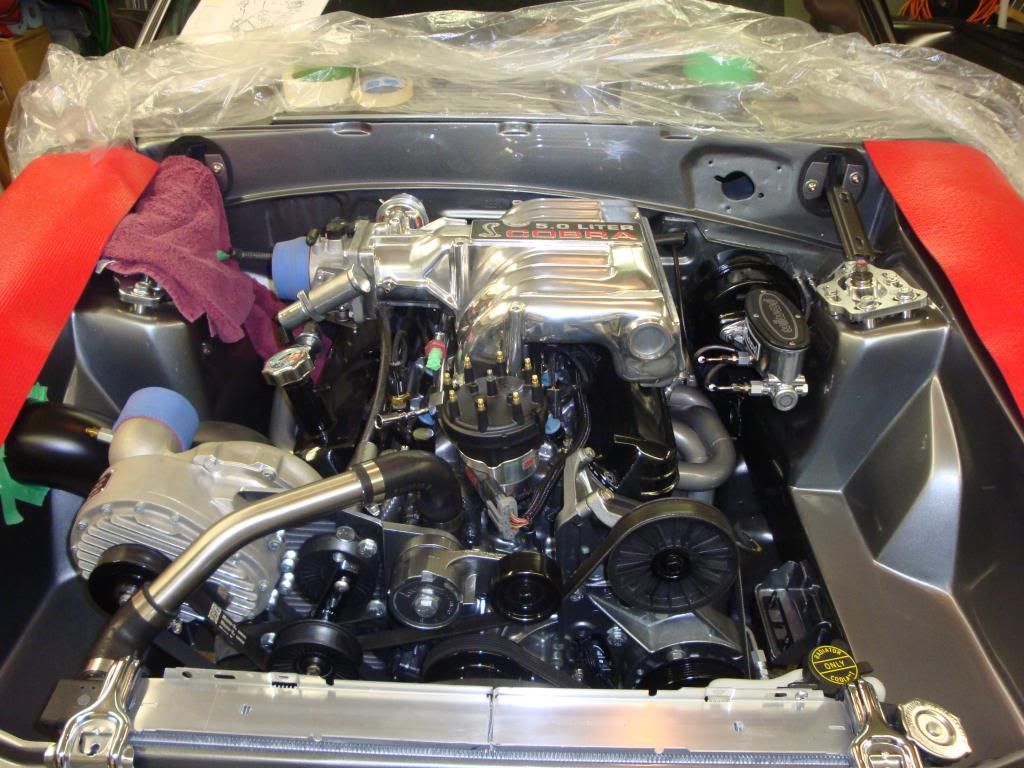
In this picture there is minimal wiring visible as the engine wiring runs under the intake and back to the firewall. Not seen in this picture, I was also able to eliminate the vacuum tree on the firewall and run directly from the engine to the brake booster with a tee off the line to provide other vacuum requirements.
This is the main engine harness in the thermal casing, leading down the top of the transmission tunnel and into the car where the two 10 pin connectors are. There is also some heat shielding on the air tube that runs between the cylinder heads. I wanted to keep all the pollution equipment functioning but hide as much as possible.
Looks awesome! This car is going to be killer!

man super nice job on this...i like that wiring cover from painless...i may have to do that now
84 Mustang GT (needs restored)
1986 True Blue Vert
Wow your really moving along fast now . Great job killer car

Wow, nice job, well thought out.

Great work!!! That thing looks awesome
65 Mustang
77 Mustang
84 GT Turbo
85 Mustang Convertible
86 Mustang LX
Thanks for the comments guys. Much appreciated. There is definitely a lot of hours in this car.
At this time, I wanted to back up a step and clarify the timeline of my pictures that show what I have done to the car over time. I started taking it apart in the fall of 2003. It went to the body shop in October 2005 and came home in July 2006. Since then, it has been at home and worked on as time has allowed. The picture of the front of the car was taken in the summer/fall of 2010. I have kept working on it on and off but sometimes other things take over for a while or sometimes you stop until you figure out how to do something or find the exact part you are looking for. The car is on the road now (as of late July 2012) but I am making sure that everything is still tight and finishing the remaining details. The picture I really want is being out on the road with other fox body owners/cars enjoying the drive.
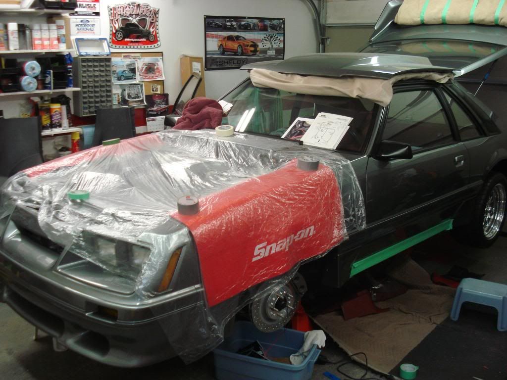
In July 2011, I put a sheet of plastic over the engine to keep it clean and switched to working on the inside of the car. This was so I could to test fit the interior panels, modify them and then drop them off at the body shop to have them colour matched (solid canyon red).
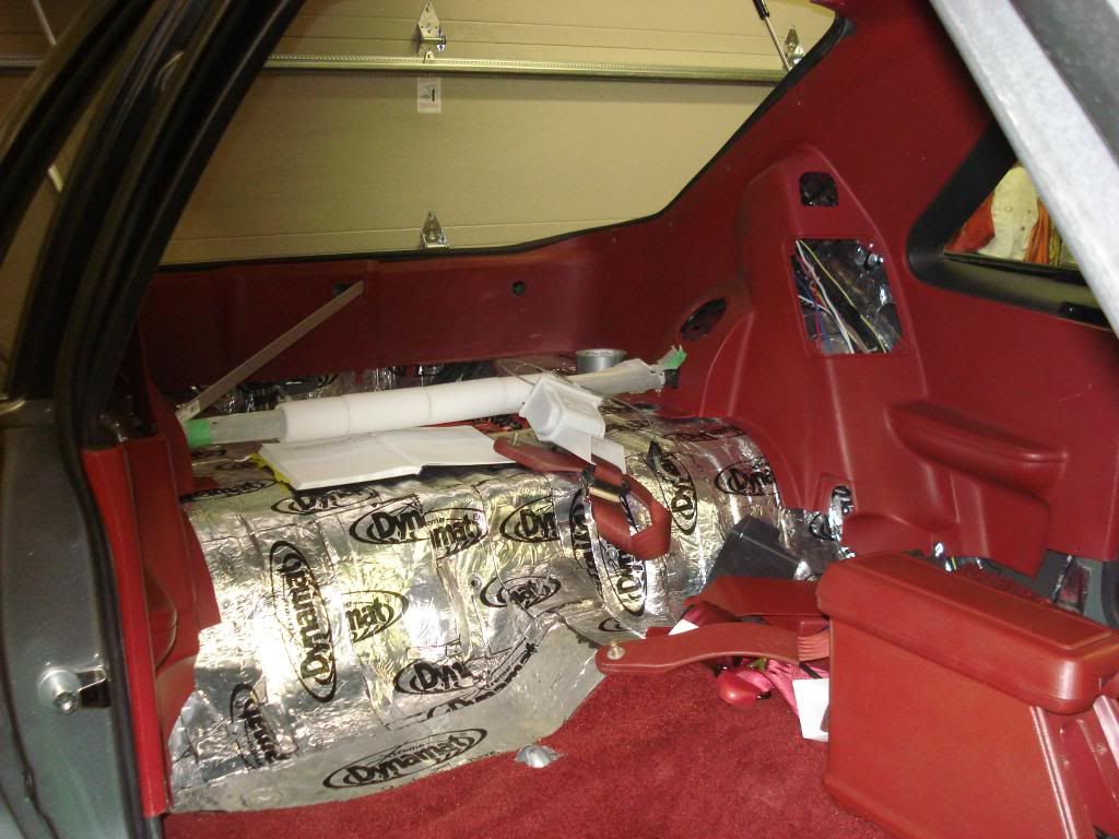
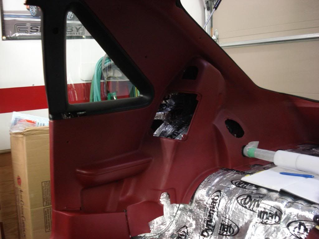
Here is the right rear quarter panel being fit into the car. The panel had to be trimmed down to fit around the ¼ window and a hole cut in it to fit around the rear shock tower brace that I had put in. When fitting these panels in place I used green tape behind all the holes in the panel. That way, I could mark where the screws would go through into the metal and drill new holes as required. In the hatch area, the quarter panel doesnt line up with the existing brackets for the screws. I made extensions for the brackets and drilled them for the new screw holes. Depending on which year ¼ panels you use, you may need to may new holes for the shoulder belt and them close off the hole not being used.
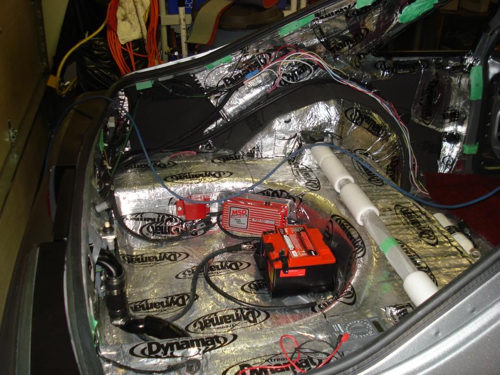
In the spare tire well, in addition to the battery, I mounted the MSD ignition and the MSD Tach adapter. To make sure the MSD would function, I talked to MSD staff and they said that what I had to do was run a wire one gauge heavier so that the signal didnt weaken going from the back of the car. The tach adapter was required because the factory tach wouldnt read correctly when I originally hooked up the MSD.
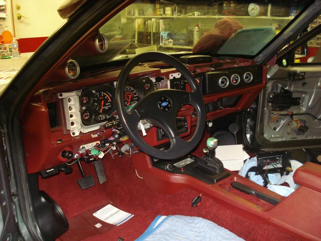
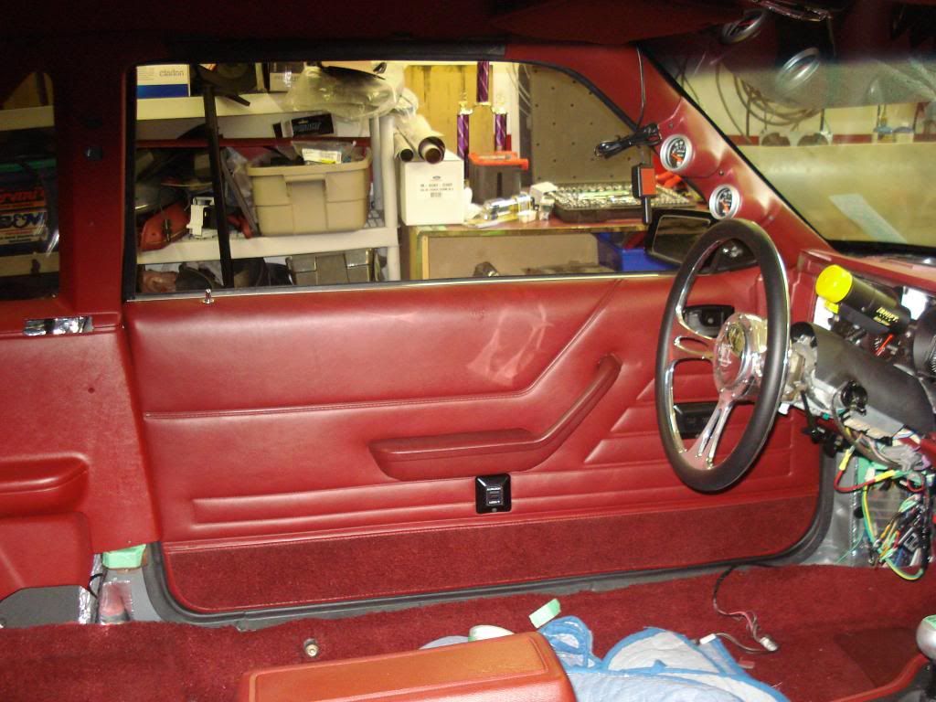
The stereo head unit is in and I am working on the enclosures for the front speakers. I didnt want to cut any holes in the door panels and the dash speakers point up at the windshield. The enclosures simply replace the front kick panels. But, when you install these, you have to remove the dead pedal for the drivers left foot. I later cut the holes out for the speakers and these were sent to be colour matched as well.
In this picture, you get another angle of the speaker enclosures. You can also see the B&M Hammer shifter with the Quicksilver shift knob for the AOD. On top of the console by the shifter there is a switch for the overdrive lockout and beside the console there is a momentary switch for the tranny brake. The AOD that I have has been fully built and can be shifted manually or automatically at any time. To upshift manually, you just move the shifter forward. You dont have to move it forward and then pull it back to keep it in the next gear.
Both ¼ panels and the rear panels have been fitted in the car. The metal ceiling panel was also test fit to make sure the screw holes lined up. At this point, most of the panels were close to being ready to be colour matched to the rest of the interior.
In August 2011, with the interior panels at the body shop, I went back to working on the engine. With the car being an automatic and no clutch cable to worry about I was able to use the clutch cable hole for the bulkhead connector for the coil wire.
After installing the bulkhead connector, this would allow me to run the coil wire from the distributor under the intake and back to the firewall. Then, another coil wire would go from the inside of the firewall and run inside the car over behind the glove compartment where the coil was mounted.
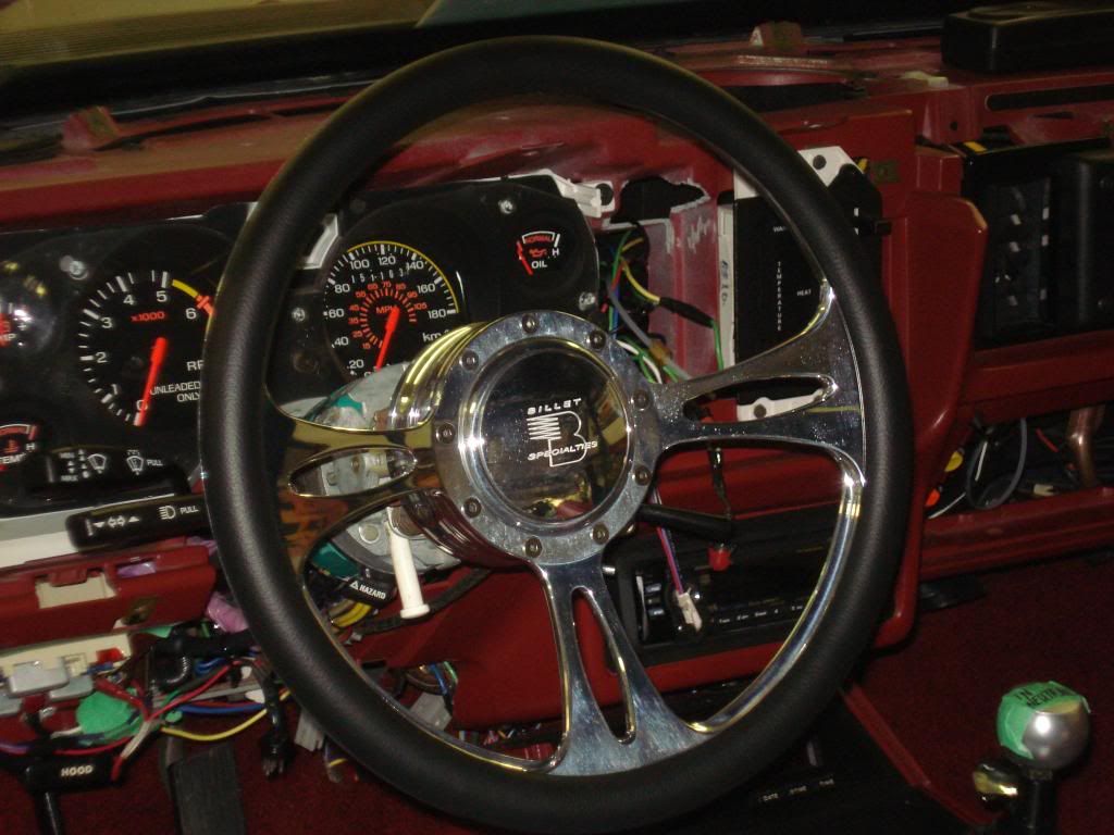
This picture shows the new steering wheel made by Billet Specialities that matches the design of the Billet Specialities Fastlane wheels. With the people that have seen the steering wheel, some like it and some prefer the original 3 spoke GT wheel. For now, Ill use this one. One issue I still have to solve is that when you use the horn, you get a shock! And it feels like a lot more than 12 volts. All suggestions are welcome to fix this one. (I thought it should be fine as it has a ground just like the original).
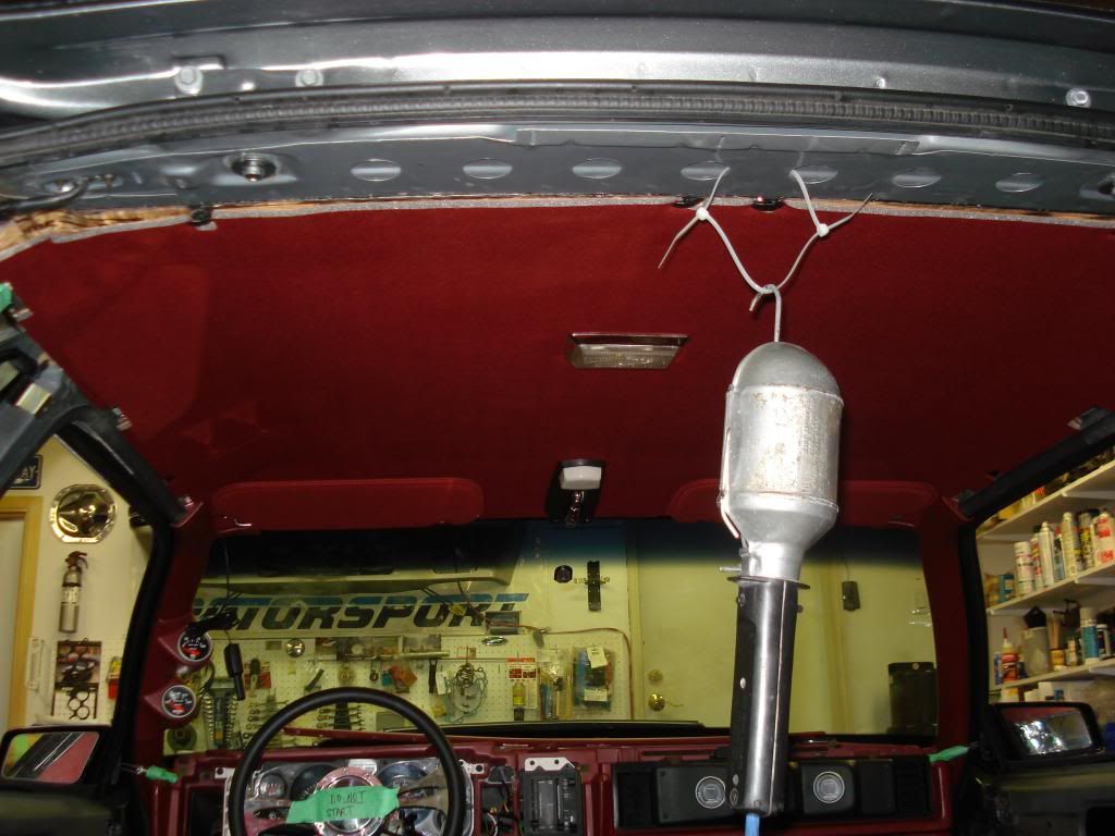
The car originally came with a vinyl headliner and vinyl sunvisors with vanity mirrors in them. I took the vinyl off the headliner board and re-did it in fabric and added fabric sunvisors from LMR.
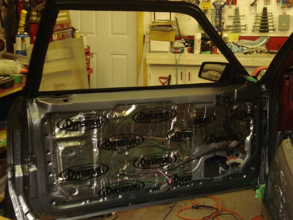
You can see inside the left rear quarter and the wheel well. Dynamat extreme was used and then the acoustic foam was used overtop in the rear 1/4s and on top of the wheel well. You can also see some of the green tape I mentioned before and the tab I had to make in the hatch area to fasten the interior panel.
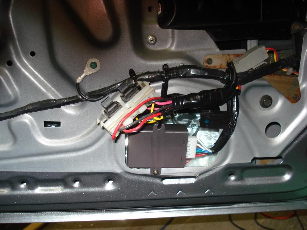
If I was to make one suggestion for anyone with a stock or modified fox body, this might be it. Autoloc makes a one touch switch that anyone with power windows can install in their car. The switch provides both one touch down and one touch up (so be careful when the window is going up). One of the upgrades I made that I really like. You can see the module in the door.
Dynamat on the door really made a difference in the sound of the car.
The door panel back on. You can also see the shift light on the steering column. This would later be relocated to inside the dash behind the middle heating vent.
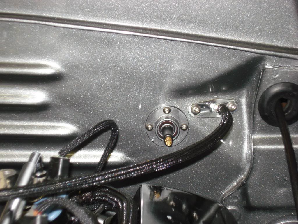
The filler neck and rear trim panel. The filler neck would later be covered in fabric to conceal it. Also, for car shows, or any time the hatch is open for a while, I installed a switch under the light on the rear trim panel to turn off the dome light when the hatch is open.
By October 2011, I had a car that was almost running but still needed an alignment. So I borrowed a buddys trailer and my dads truck and got it done. The catch was, the car didnt run. So at the alignment shop, with a little bribing (pizza lunch for the staff) they helped me push the car in to the alignment bay. Then the car was rolled out and over to the trailer. Thank heavens for the power winch to get it back on the trailer. Then the next stop was to get the windows tinted. But, while pushing the car around, I found out (almost the hard way) that the tire size I had chosen for the front (BFG 245/45/17) on the 8 wheels didnt allow me to turn the wheels lock to lock. So, I had to buy new tires (245/40/17s) for the front. Next issue, the new tires had the new tread pattern, not the traditional tread. So, to get everything to match, I then had to buy new rear tires (BFG 275/40/17) to put on the 9.5 wheels. I was lucky because a friend of mine just happened to be looking for new tires for his 92 5.0L convertible. (This was an interesting way to find out that the newer cars have larger wheel wells. So double check your wheel and tire sizes carefully). You can see the new tires in the picture.
So, late October 2011, I finished up what I needed to make it run. With dry roads and sunshine, everything working, a partial dash, unfinished interior, engine compartment almost done and no plastic fender linings, I took the car for the first drive in 8 years. That 20 minute drive left me with a smile on my face that lasted for months.
So, at this point the car is almost up to date but there is more interior work that I'll post.

Great thread and a well thoughtout build. I'm glad to see you kept the red interior but sad to see the look of the 84 go
Current Stangs+
84Gt (9W) T-top 347EFI
http://www.foureyedpride.com/content...984-Mustang-GT
84Gt(1E)Hardtop Turbo
http://www.foureyedpride.com/content...e-of-the-Month

wow man this has been great to watch, I'd love to see a video to hear her run.
One question, about the filler neck looks like it goes uphill before going into the gas tank wont gas collect there?
My facebook:
http://www.facebook.com/ahgrafx
Artwork:
http://www.addictedtopixels.com
http://www.addictedtopaint.com

If you have a problem with timing MSD has had alot of trouble with the distributor you have...I had one in my car and changed it for a stock one picked up 45 hp at the wheels...you can have it ..very nice job on the car..
Mike
Last edited by 86-199; 02-20-2013 at 01:51 AM.
Mike
85 saleen 014 1st Red Saleen and 7th car built..
86 Saleen 199 Black
86 Saleen 200 Black Convertible
Black isn't a color it's a Statement


Awesome build. Subscribing.
13 Dodge Dart
09 Shadow Sabre
08 Caliber
05 Aztek
02 Avalanche
02 Thunderbird
01 Cadillac ETC
98 Explorer
96 Suzuki X-90
89 Fleetwood
89 Continental
88 Town Car
86 Silverado
84 Fiero
83 Town Car
82 LN7
82 EXP
80 Mustang
65 Continental
62 Galaxie 500
54 Packard
Stock never goes out of style.
Wow Im lost for words its such a sweet ride I under stand why cars like this take so long to build such a huge amount of planing and labor . Its great to see pics of cars like this being built it give lost of good ideas to others you did a first rate job
Thanks for the comments. I also like the look of the 84 and wish I could have both. But for this time the 85/86 look was closer to what I wanted to end up with.Originally Posted by EVIL8286

I hope to fire it up in about a week and will try to do a video of it running. It must have been the camera angle on the filler neck. It is level, but I may modify it because the pumps at some gas stations don't fit properly. I would have thought they were all the same.
Mike, I hadn't heard of any problems with these distributors before now. But maybe I'll keep my stock distributor just in case. I know that some of the MSD ignition coils are loud (make a humming sound). I tried two different styles of MSD coil before I found a quiet one. Thanks for the info.
The thing that made a big difference to my car after the EFI was in it was the speed sensor on the speedometer. Before, the car thought I was reving it in neutral and not under load. After I put one in and wired it into the computer, I blew the rear tires off it.
 Posting Permissions

 Reply With Quote
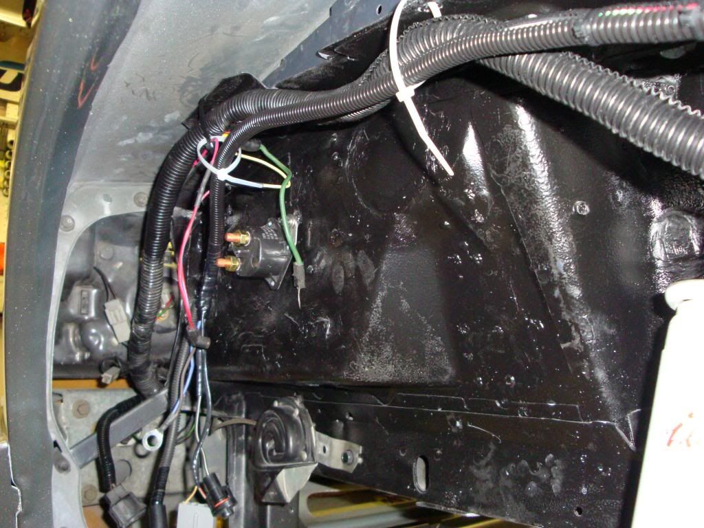

Connect With Us